Installation, A-11, Power wave® ac/dc 1000 – Lincoln Electric IM848 POWER WAVE AC_DC 1000 User Manual
Page 21
A-11
INSTALLATION
POWER WAVE® AC/DC 1000
A-11
A
R
C
11
A
RC
2
AR
C
2
AR
C
3
A
R
C
1
A
R
C
3
A
R
C
1
A
R
C
2
A
R
C
3
S
Y
S
T
E
M
I
N
T
E
R
F
A
C
E
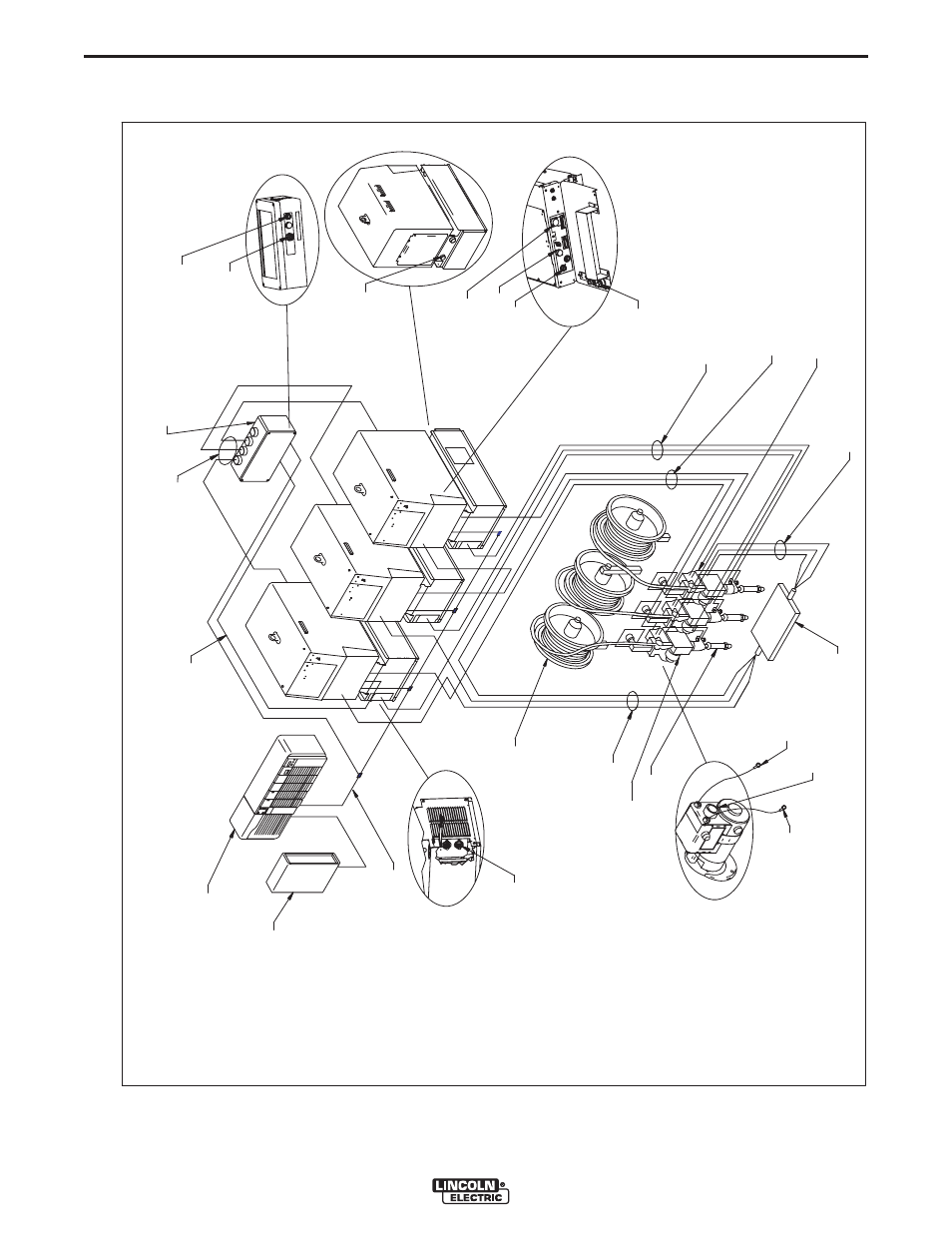
Connection Diagram- Typical Triple Arc System (DeviceNet PLC Controller)
67 Lead
21 Le
ad
14 P
in
Co
nnector
* Work Ca
bles
Work P
iece
Work
S
ense L
eads (2
1)
* E
lectrod
e Cables
* Ref
er to
"Ou
tp
u
t Cable G
uidel
ines" f
or reco
m
m
e
n
de
d cable s
ize.
Head
K
231-
XX
X
Devi
ceNe
t Ca
bl
e
Ne
tw
or
k
K
179
5-
X
X
C
abl
es
K
154
3-
X
X
Arc
link Co
ntrol Cab
le
K
178
5-
XX
Wir
e Feeder
Contro
l Cab
les
Arc
link Input
Wir
e Feeder
(14 P
in)
Arc
link (5
P
in)
Work Stu
ds
E
lectrod
e Stu
ds
W
ire
Re
el
an
d
Mou
n
tin
gs
P
LC Contro
ller
E
lectrod
e S
ense L
ead (6
7)
Master Input (S1
2)
Con
nects to System
Interface
K22
82-1
User
I
n
terf
ace
Device
Net
Device
Net
(5 P
in)
See also other documents in the category Lincoln Electric Equipment:
- Invertec V310-T DC (2 pages)
- VANTAGE 500 (CE) 11575 (50 pages)
- INVERTEC V350-PRO SVM152-A (155 pages)
- IMVERTEC V160-T (36 pages)
- IDEALARC CV-300 (112 pages)
- INVERTEC POWER WAVE 450 SVM112-B (293 pages)
- AUTO-DARKENING HELMET IM10001 (12 pages)
- IM10111 IDEALARC R3R-500-I (28 pages)
- IM10110 IDEALARC R3R-400 (25 pages)
- IM10051 INVERTEC V311-T AC_DC (38 pages)
- IM10059 SQUARE WAVE TIG 175 (30 pages)
- IM10096 POWER MIG 256 (37 pages)
- IM10096 POWER MIG 256 (38 pages)
- IM10105 POWER MIG 350MP (47 pages)
- IM10115 FLEXTEC 650 (42 pages)
- IM10132 FLEXTEC 650 (56 pages)
- IM10132 FLEXTEC 650 (36 pages)
- IM10018 IDEALARC DC-600 VRD (55 pages)
- IM10107 IDEALARC DC-400 (40 pages)
- IM10062 FLEXTEC 450 (72 pages)
- IM10091 FLEXTEC 450 CE (40 pages)
- IM10094 RED-D-ARC FX450 (31 pages)
- IM10157 12_24V 10A Auto HF Household Charger (16 pages)
- IM10139 JUMP STARTER (12 pages)
- IM10149 POWER WAVE ADVANCED MODULE (46 pages)
- IM10102 AIR VANTAGE 650 (60 pages)
- IM10103 AIR VANTAGE 700 (AU) (57 pages)
- IM10065 AIR VANTAGE 500 CUMMINS (54 pages)
- IM10066 AIR VANTAGE 500 (AU) (56 pages)
- IM10041 VANTAGE 500 CUMMINS (56 pages)
- IM10128 AIR VANTAGE 500 KUBOTA (AU) (56 pages)
- IM10090 ARC TRACKER (48 pages)
- IM10147 AUTO-DARKENING HELMET (12 pages)
- IM10087 AutoDrive 19 CONTROLLER (28 pages)
- IM10125 AutoDrive 19 TANDEM (34 pages)
- IM10069 AutoDrive 4R100 (32 pages)
- IM10145 AUTOPRO 20 (24 pages)
- IM10025 BIG RED 500 (40 pages)
- IM10019 BIG RED 600 (41 pages)
- IM10005 BULLDOG 140 (46 pages)
- IM10074 BULLDOG 5500 (56 pages)
- IM10067 CENTURY AC120 (20 pages)
- IM10109 CIRCULATOR (33 pages)
- IM10109 CIRCULATOR (36 pages)
- IM10153 CLASSIC 300 HE (60 pages)