Operation, Controls and settings – Lincoln Electric IM560 POWER-ARC 5000 User Manual
Page 19
B-3
OPERATION
B-3
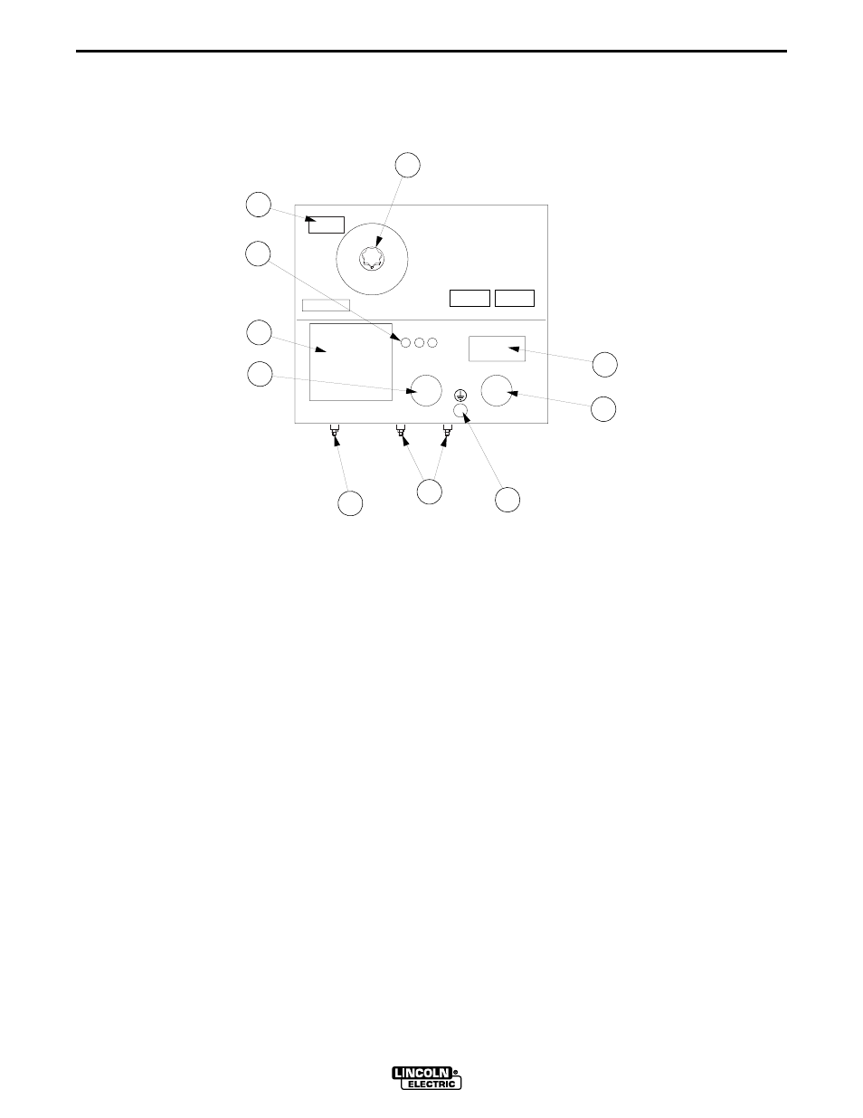
GENERATOR/WELDER CONTROLS
See Figure B.1 for the location of the following fea-
tures:
1.
CURRENT CONTROL DIAL: Adjusts continuous
current output. The amperages on the dial corre-
spond to the average amperages needed for spe-
cific Lincoln welding electrodes.
2.
ELECTRODE SELECTION GUIDE: Provides rec-
ommended electrodes.
3.
WELD OUTPUT TERMINALS (TO ELECTRODE
HOLDER, HIGH RANGE AND LOW RANGE): Pro-
vides the connection point for the electrode hold-
er cable.
4.
WELD OUTPUT TERMINAL (TO WORK):
Provides the connection point for the work cable.
5.
GROUNDING TERMINAL: Provides a connection
point for connecting the machine to earth ground
for the recommended grounding procedure.
6.
CIRCUIT BREAKERS (3): Provides separate
overload current protection for the 120 volt and
120/240 volt receptacles.
7.
15 AMP, 120 VOLT GFCI DUPLEX RECEPTACLE:
For supplying 120 volt power to operate one or
two electrical devices.
8.
30 AMP, 120 VOLT TWIST-LOCK RECEPTACLE:
120 volt power for higher power requirements.
9.
30 AMP, 120/240 VOLT TWIST-LOCK RECEPTACLE:
For supplying 240 volt power and for connection
to 120/240 volt premises wiring.
10. ENGINE HOUR METER: Records engine running
time. Use this meter to schedule engine mainte-
nance.
POWER ARC 5000
POWER ARC 5000
1
7
8
5
3
4
2
6
9
10
120 VOLTS 15 AMPS
120 VOLTS 30 AMPS
120/240 VOLTS 30 AMPS
CIRCUIT BREAKERS
WORK
LOW RANGE HIGH RANGE
WARNING
WELDING ELECTRODES
FIGURE B.1 – OUTPUT PANEL CONTROLS
1. CURRENT CONTROL DIAL
2. ELECTRODE SELECTION GUIDE
3. WELD OUTPUT TERMINALS (TO ELECTRODE HOLDER, HIGH RANGE AND LOW RANGE)
4. WELD OUTPUT TERMINAL (TO WORK)
5. GROUNDING TERMINAL
6. CIC. GFCI DUPLEX RECEPTACLE - 120 VOLT, 15 AMP
7. GFCI DUPLEX RECEPTACLE - 120 VOLT, 15 AMP
8. TWIST-LOCK RECEPTACLE - 120 VOLT, 30 AMP
9. TWIST-LOCK RECEPTACLE - 120/240 VOLT, 30 AMP
10.ENGINE HOUR METER
CONTROLS AND SETTINGS
All generator/welder controls are located on the Output Control Panel. Gasoline engine controls are mounted on
the engine. See Figures B.1 and B.2 and the explanations that follow.