Installation, Voltage sensing, Caution – Lincoln Electric IM916 POWER FEED 10M Dual WIRE FEEDER User Manual
Page 12
A-4
INSTALLATION
POWER FEED
®
10M DUAL WIRE FEEDER
A-4
VOLTAGE SENSING
The best arc performance occurs when the Power
Waves
®
have accurate data about the arc conditions.
Depending upon the process, inductance within the
electrode and work lead cables can influence the volt-
age apparent at the studs of the welder. Voltage
sense leads improve the accuracy of the arc condi-
tions and can have a dramatic effect on performance.
Sense Lead Kits (K940-xx) are available for this pur-
pose.
If the voltage sensing is enabled but the sense
leads are missing, improperly connected, or if the
electrode polarity switch is improperly configured,
extremely high welding outputs may occur.
------------------------------------------------------------------------
The ELECTRODE sense lead (67) is built into the
control cable, and is automatically enabled for all
semi-automatic processes. The WORK sense lead
(21) connects to the Power Wave
®
at the four pin con-
nector located underneath the output stud cover. By
default the WORK voltage is monitored at the output
stud in the Power Wave
®
455. For more information on
the WORK sense lead (21), see"Work Voltage
Sensing” in the following paragraph.
Enable the voltage sense leads as follows:
TABLE A.2
Process Electrode Voltage
Work Voltage
Sensing 67 lead *
Sensing 21 lead
GMAW
67 lead required
21 lead optional
GMAW-P 67 lead required
21 lead optional
FCAW
67 lead required
21 lead optional
GTAW
Voltage sense at studs
Voltage sense at studs
GMAW
Voltage sense at studs
Voltage sense at studs
SAW
67 lead required
21 lead optional
CAC-C
Voltage sense at studs
Voltage sense at studs
* The electrode voltage 67 sense lead is integral to
the control cable to the wire feeder.
CAUTION
The Power Feed
®
10M Dual Wire Feeder is factory set
for Electrode Positive welding.
Most welding procedures use Electrode Positive weld-
ing. Some Innershield procedures may use Electrode
Negative welding. For most applications, the Power
Feed
®
10M Dual Wire Feeder will have both sides of
the Wire Drive set to the same polarity. To weld with
opposite polarities, each head would have to be weld-
ing on isolated work pieces and the weld cable attach-
ing the two feed heads would have to be removed.
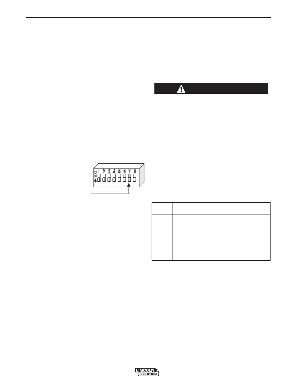
To change the DIP switch inside the Power Feed
®
10M Dual Wire Feeder for electrode polarity:
1. Turn off power at the welding power source.
2. Remove the rear access panel on the wire drive.
3. Locate DIP switches on BOTH Wire Drive Boards.
4. Set DIP switch #7 on BOTH Wire Drive Boards to
the desired polarity.
DIP Switch #7 Position
Polarity
ON (Up)
- (negative) polarity
OFF (Down) + (positive) polarity
5. Assemble the rear access panel to the wire drive.
6. Restore power.
}