Operation, Spring tension arm, Internal controls – Lincoln Electric IM824 LN-15 WIRE FEEDER User Manual
Page 19
B-5
OPERATION
LN™-15 CONTROL CABLE MODEL & (CE)
B-5
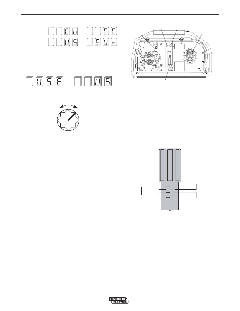
Rotate the WFS knob until the desired parameter is
displayed.
CV/CC Mode:
WFS Units:
2. Activate and release the GAS PURGE switch to
select the parameter. The present value will then
display in the right hand side of the display.
Example:
3. Rotate the WFS knob to change the parameter set-
ting.
CV/CC Mode:
• "CU" for Constant Voltage power sources
• "CC" for Constant Current power sources
WFS Units:
• "US" for in/min
• "Eur" for m/min
4. Press the GAS PURGE switch to save the setting.
The LN™-15 will then return to the original "Press
Spin" mode in step 1.
5. To exit the "Press Spin" set-up mode, turn off power
to the LN™-15, or simply wait 15 seconds and the
LN™-15 will enter normal operation.
WFS
SPRING TENSION ARM
The pressure arm controls the amount of force the drive
rolls exert on the wire. Proper adjustment of both pres-
sure arm gives the best welding performance. For best
results, set both pressure arms to the same value.
Set the pressure arm as follows (See Figure B.2a):
Aluminum wires
between 1 and 3
Cored wires
between 3 and 4
Steel, Stainless wires
between 4 and 6
Figure B.2a
FLOWMETER
SPRING
TENSION
ARM
COLD FEED/
GAS PURGE
SWITCH
2 STEP/TRIGGER
INTERLOCK
SWITCH
SPINDLE
BRAKE
INTERNAL CONTROLS
(Figure B.2)
ALUMINUM
OUTERSHIELD
METALSHIELD
INNERSHIELD
STEEL
STAINLESS
CORED WIRES
SOLID WIRES
6
1
3 2
5 4