Figure 5 - feed head component orientation – Lincoln Electric IM614 Aluminum Drive Roll Kits User Manual
Page 6
KP1507 SERIES ALUMINUM DRIVE ROLL KIT
6
6
Remove Item 6 (Spring Retaining Rod) by grasp-
ing Item 12 (Adjustment Knob) and sliding it out of
Item 1 (Pressure Door). Item 10 (Plastic Thrust
Washers) and Item 11 (Steel Thrust Washer) will
also be removed along with Item 6 (Spring
Retaining Rod).
7.
Remove Item 7 (Springs) from Item 1 (Pressure
Door)
Note: Be sure to save these springs for converting
the Wire Feeder back to feeding solid steel or
cored steel wire. Use these instructions for the
conversion.
Reassembly with new springs:
8.
Slide Item 6 (Spring Retaining Rod) into Item 1
(Pressure Door) until it is just past the first Item 2
(Pressure Arm)
Note: Item 12 (Adjustment Knob), Item 10 (Plastic
Thrust Washers), and Item 11 (Steel Thrust
Washer) should still be on Item 6 (Retaining Rod)
9.
Place 1 Item 13 (Steel Thrust Washer supplied
with kit) and 1 Item 7 (Spring supplied with Kit)
over Item 6 (Spring Retaining Rod).
Note: Be sure that the springs being installed are
for the proper type of wire to be fed. (Light springs
for aluminum, heavy springs for steel)
10 Continue to slide Item 6 (Spring Retaining Rod)
into Item 1 (Pressure Door) until it is just past the
second Item 2 (Pressure Arm).
11. Repeat Step 9 and then go to step 12.
12. Continue to slide Item 6 (Spring Retaining Rod)
into Item 1 (Pressure Door) until Item 12
(Adjustment Knob) is seated against Item 1
(Pressure Door).
13. Slide Item 7 (Springs) and Item 13 (Steel Thrust
Washers) until they are against each of Item 2
(Pressure Arm).
14. The threaded hole in item 6 (Spring Retaining
Rod) nearest item 12 (Adjusting Knob) should be
lined up with the hole in item 9 (Indicator). Thread
item 8 (#6-32X1.00 Socket Head Cap Screw) into
and thru item 6 (Spring Retaining Rod) and then
approximately 2 turns into item 9 Indicator.
Note: If the threaded hole and indicator are NOT
lined up turn item 12 (Adjustment Knob) as
required clockwise or counter clockwise to adjust
the position of the threaded hole in item 6 (Spring
Retaining Rod) until it lines up with the indicator or
gently slide the indicator using the end of the 7/64
Hex Key Wrench until it is lined up.
15. Thread the other item 8 (#6-32X1.00 Socket Head
Cap Screw) into and thru the other threaded hole
in item 6 (Spring Retaining Rod) until it bottoms
on item 1 (Pressure Door) and then back off
approximately 1 turn.
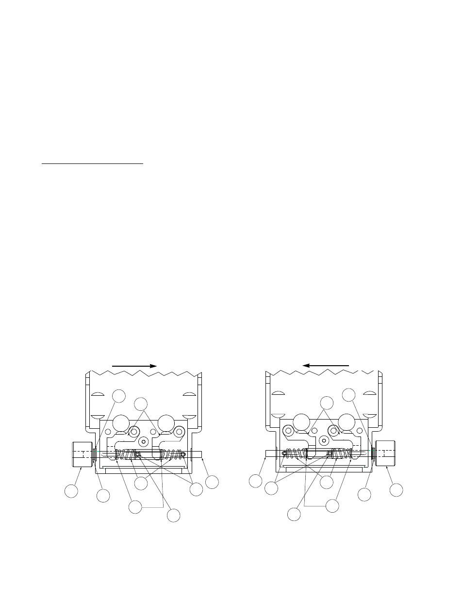
16 Before continuing, use the diagrams in figure 5 to
check the orientation and position of items
2,6,7,8,9,10,11,12, and 13.
10
11
12
6
2
8
13
7
9
10
11
12
6
2
8
13
7
9
Left Side Feed Head
Orientation
Dual Head Feeders Only
(Left as viewed from front of wire feeder)
Right Side Feed Head
Orientation
Dual & Single Head Feeders
Figure 5 - Feed Head Component Orientation
Direction of wire feeding
Direction of wire feeding