Installation instructions, Warning – Lincoln Electric IM614 Aluminum Drive Roll Kits User Manual
Page 3
KP1507 SERIES ALUMINUM DRIVE ROLL KIT
3
INSTALLATION INSTRUCTIONS
The installation instructions are divided into three sec-
tions:
1. Conduit bushing and conduit installation
2. Drive roll and wire guide installation
3. Pressure door spring installation (all kits except
KP1507-3/32A).
Note: Installation of the included pressure door
springs is not required, but is recommended for opti-
mum wire feeding performance.
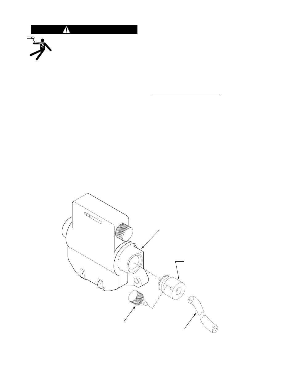
1. CONDUIT AND BUSHING
INSTALLATION
Refer to figure 2 and follow the following steps:
1. Turn off the welding power source.
2.Loosen the set screw which secures the existing
incoming guide bushing and remove the bushing.
3. Thread the thumb screw into the new bushing.
Install the new conduit bushing into the wire feed
head.
Recommended Conduit Length:
Power Feed 10
13.0 in.
(330 mm) as provided
LN-10, STT-10
11.5 in.
(290 mm)
DH-10
10.0 in
(250 mm)
Power Feed 11
1.0 in
(25 mm)
4. FOR LINCOLN CONDUIT: Measure the conduit
and cut to the desired length. A tubing cutter makes
the best cut. A hacksaw or utility knife may also be
used.
5. Back out the thumb screw from the bushing insert
the conduit. Tighten the thumb screw. The thumb
screw threads will lock the conduit in place.
ELECTRIC SHOCK Can Kill
• Only qualified persons should perform
this installation.
• Turn off the welding power source before installing
or changing drive rolls or guides.
• When inching with the gun trigger, the electrode and
drive mechanism are electrically “hot”.
------------------------------------------------------------------------
WARNING
Figure 2 - Conduit Bushing and Conduit Installation
Feed Head
Knurled Knob
Item 6
Conduit Bushing
Item 4
Set screw
location
Conduit
Item 7