Lincoln Electric IM480 CV-400 User Manual
Page 20
–
20
–
OUTPUT CONTROL “LOCAL-REMOTE” SWITCH
The Output Control toggle switch on the control panel
labeled “Local-Remote” gives the operator the option
of controlling the output at the machine control panel
or at a remote station. For remote control, the toggle
switch is set in the “Remote” position and controlled at
the wire feed unit control, or by connecting a K775
control to terminals 75, 76, and 77 on the terminal
strip at the front of the machine, or by connecting a
K857 control with a K864 adapter to the 14-pin con-
nector on the front of the machine. For control at the
machine control panel (Output Voltage control dial),
the toggle switch is set in the “Local” position.
(Exception: When used with an LN-9, LN-9 GMA or
NA-5 wire feeder, the Output Control switch must be
in the “Remote” position or automatic shutdown of the
LN-9 or NA-5 may occur.)
POLARITY SELECTION
Polarity selection is made by appropriately connecting
the electrode and work welding cables to either the
“
+
” stud or to the “
-
” stud. Select “Voltmeter” switch
for “
+
” or “
-
” electrode for the remote (#21) work sens-
ing lead.
VOLTMETER SWITCH
Select “
+
” for positive electrode or “
-
” for negative
electrode. This switch selects electrode polarity for the
remote (#21) work sensing lead of automatic or semi-
automatic equipment.
THERMAL PROTECTION LIGHT
The amber thermal protection light will be lit if either of
the two protective thermostats have opened. The out-
put power will be disabled but input power will still be
applied to the welder.
115 VAC and 42 VAC AUXILIARY POWER AND
CONTROL CONNECTIONS
14-Pin Connector
The 14-pin connector receptacle (type MS-3102A-2D-
27SX) supplies auxiliary power.
42 VAC is available at receptacle pins I and K.
A 10 amp circuit breaker protects this circuit.
115 VAC is available at receptacle pins A and J. A 10
amp circuit breaker protects this circuit. Note that the
42 VAC and 115 VAC circuits are electrically isolated
from each other.
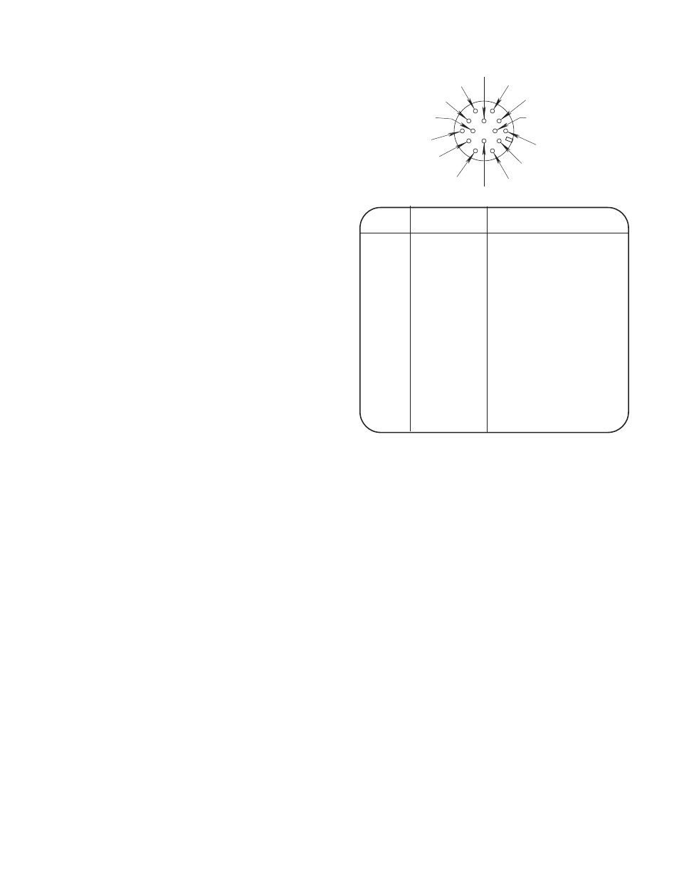
FRONT VIEW OF 14-PIN CONNECTOR
RECEPTACLE
PIN
LEAD NO.
FUNCTION
A
32
115 VAC
B
GND
Chassis Connection
C
2
Trigger Circuit
D
4
Trigger Circuit
E
77
Output Control
F
76
Output Control
G
75
Output Control
H
21
Work Connection
I
41
42 VAC
J
31
115 VAC
K
42
42 VAC
L
---
---
M
---
---
N
---
---
F = 7 6
G = 7 5
H = 2 1
I = 4 1
J = 3 1
K = 4 2
A = 3 2
B = G N D
C = 2
D = 4
E = 7 7
L
N
M