Ariens 927046-056 User Manual
Page 27
7 - 27
7.2 SPEED SELECTOR
Carrier Assembly Removal
1. Remove cotter pin attaching shift link to bellcrank
and disconnect shift link from bellcrank.
2. Remove spring from clutch shaft.
3. Remove cotter pin from one end of transfer shaft
and remove transfer shaft from frame.
4. Unhook carrier yoke from clutch shaft and remove
yoke and carrier assembly.
Disassembly of Carrier
1. Remove locknut and thrust washer from top of
spindle bolt.
2. Remove drive disc assembly from bearing housing
along with ball bearings and sleeve bushing.
3. Remove two flange whizlock screws attaching
yoke to carrier and remove yoke.
4. Remove two flange whizlock screws attaching
bearing housing to carrier and remove bearing
housing.
5. Remove shim washer from spindle bolt.
6. Remove four flange whizlock screws securing disc
adapter to drive disc and remove adapter and
spindle bolt.
7. Inspect all parts for wear or damage and replace
as necessary.
8. Assemble in reverse order.
NOTE: Center lock nut at top of assembly must be
torqued to 45 ft-lbs (61 Nm).
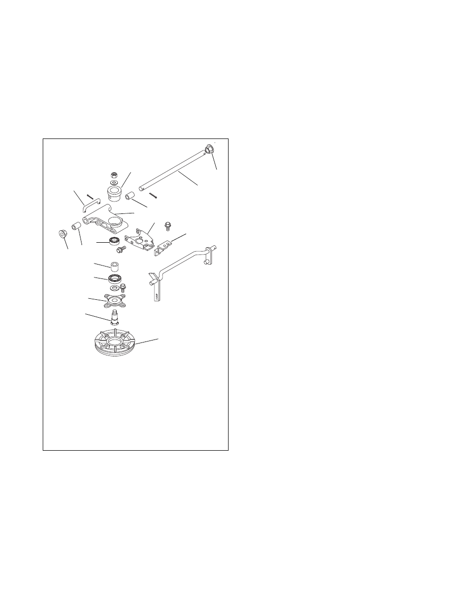
Figure 26
1. Flange Bushing
2. Transfer Shaft
3. Sleeve Bushing
4. Drive Plate Carrier
5. Carrier Yoke
6. Neutral Stop
7. Ball Bearing
8. Sleeve Bushing
9. Radial Bearing
10.Drive Disc Adaptor
11.Spindle Bolt
12.Drive Disc
13.Shift Link
14.Bearing Housing
1
2
3
4
5
6
7
8
9
10
11
12
13
14
1
3