Davey PRIME JET 240 PUMPS AND PRESSURE SYSTEMS User Manual
Page 5
PRESSURE SWITCH SETTING (Applicable to Pressure System Models Only.)
Shallow Well Installations
For installations with shallow well jet kits it is necessary to set the pressure switch cut in and cut
out settings according to the table below. Instructions for altering the pressure switch setting are
under the cover of the switch.
MODEL
Shallow Well Jet Kit
Pressure Switch Setting
kPa
psi
Prime
680
240-370
35-54
Jet
681
300-470
44-68
240
682
400-590
58-86
683
500-690
73-100
Deep Well Installations
Pressure systems to be installed with deep well injectors need no adjustment to the pressure
switch as the factory setting is satisfactory for all deep well injectors (210-350kPa, 30-50psi).
PUMP CONNECTIONS
(A) Pumps to be operated as Automatic Pressure Systems:
* Connect hose kit to Davey Supercell Pressure Tank and to bottom of outlet tee on pump as
shown in illustration. Firm tightness should be sufficient. Ensure tank connection hose is not
kinked.
* Fit gate valve to outlet tee of pump using thread seal tape.
* Connect delivery piping at gate valve.
* Fit pressure gauge on top of pump.
(B) Pumps to be operated Manually at Power Point:
* Disconnect pressure switch barrel union on top of pump then screw stainless steel self tapping
screw into pressure switch port to block it off.
* Reconnect barrel union.
* Fit gate valve to pump outlet (1
1
/
4
” Female) using thread seal tape.
* Connect delivery piping at gate valve.
* Fit pressure gauge on top of pump. A non-return valve may need to be fitted in the delivery
piping on some installations to prevent water siphoning back through the pump. Consult your
Davey Dealer or the Davey Customer Service Centre.
PRESSURE TANK PRE-CHARGE (Applicable to Pressure System Models Only.)
The Supercell pressure tank requires the correct pre-charge of air for satisfactory operation. This
pre-charge of air is determined by the cut-in pressure switch setting for the particular system
purchased. Prime Jet 240 Supercell 30 Pressure Tanks are factory pre-charged to 245kPa (35psi)
which is suitable for a pressure switch cut in of 230kPa (33psi). To adjust for a higher cut in
pressure setting add air at the valve on top of the tank until the pressure is 15kPa (2psi) below the
proposed pressure switch cut in. Adjust this pre-charge before installing the pressure system.
A gate valve must be fitted at the outlet of all pumps prior to the connection of
outlet piping.
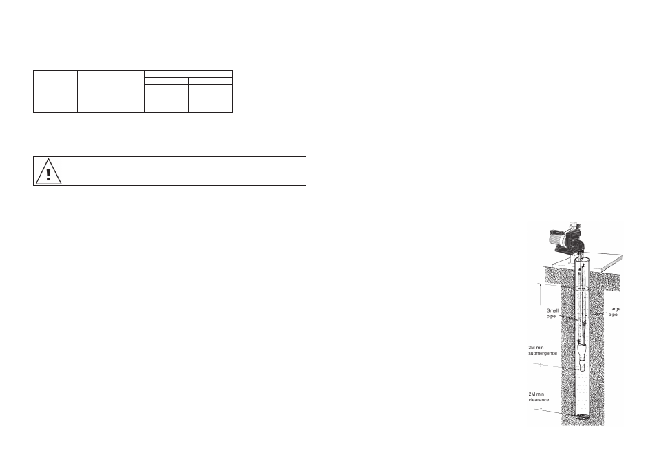
(B) Plumbing Details for Deep Well Injectors.
A minimum submergence of 3m (10 ft.) is required for the injector and foot valve assembly for
correct operation.
When water is pumped out from a borehole it is common for the water level in the bore to drop.
However, there is usually a point at which the bore water level remains static or constant for a
given maximum flow from the bore. This new level is known as the draw down level of the bore.
It is necessary to establish this draw down level and the output capacity of the bore at this level
before installing a pump on the bore.
Once the pump has been installed on the bore it is necessary to regulate the flow from the pump
to ensure it does not exceed the maximum capacity of the bore at the draw down level. (Refer to
Operating Instructions included with Deep Well injectors).
The minimum submergence of the injector and foot valve assembly of 3 metres (10 ft.) means the
length of piping required from top of bore to injector assembly is equal to the draw down level plus
3 metres (10 ft.).
Furthermore, ensure that at least 2 metres (6 ft.) clearance exists between the injector assembly
and the bottom of the bore.
Having established the length of the piping required for attachment to the injector, connect the
injector assembly making sure that the larger pipe is fitted to the long venturi tube of the injector.
Use 2 hose clips on each pipe connection and tighten securely. It may be necessary to heat the
polythene piping slightly before pushing it on to the hose tails. At the other end of the suction
pipes (top of bore end) fit the adaptor flange to the piping using the hose tail connectors provided
loose in the injector kit.
Ensure joints are air tight, thread seal tape or pipe joining
compound is recommended. Securely tighten 2 hose clips on
each connector.
It is essential that there be no air leaks at this connection
particularly because air leaks are the biggest cause of
suction and priming difficulties. Air being sucked in is almost
impossible to detect. Ensure that both pipes are of even length
and will lie straight side by side before installing in the bore
hole.
Lower injector assembly into bore hole and attach adaptor
flange to pump using the rubber gasket provided. Tighten the
nuts sufficiently to prevent air leaks around the gasket but do
not over-tighten.
- 8 -
- 5 -