Davey PRIME JET 240 PUMPS AND PRESSURE SYSTEMS User Manual
Page 3
To Check Correct Operation Of A Pressure System With Pressure Tank Fitted
Close gate valve at pump outlet. Allow pump to run and build up pressure until it switches off
automatically at the cut-out pressure setting on the pressure switch.
Open gate valve on pump outlet then turn on a tap in the outlet pipework. Pump should
automatically switch on at cut-in pressure switch setting. Refer to the “Pressure Switch Settings”
section earlier in these instructions.
MINIMUM OPERATING PRESSURE FOR DEEP WELL INSTALLATIONS
INJECTOR KIT NO.
427
428
468
566
567
568
569
Minimum Operating
Pressure kPa
280
280
280
270
270
290
240
Automatic Demand Response (ADR) - Setting up instructions
Deep Well installations require a certain minimum pump pressure to operate satisfactorily
(See Table above). With the adjustment screw on the ADR valve adjusted fully out run the pump.
Open gate valve (situated near pump) to discharge water freely until pressure on gauge drops
to minimum operating pressure as table above or until pump nears cavitation point. Screw ADR
valve adjustment in until pressure starts to rise. Open gate valve a little further, then readjust ADR
valve to maintain required minimum pressure on gauge. When gate valve is fully open and ADR
valve is maintaining operating pressure, adjustment is complete.
Once set, there should be no need to alter the setting of the ADR valve. ADR valve should be set
by discharging water adjacent to pump before connecting outlet pipework or pressure tank.
MINIMUM OPERATING PRESSURE FOR SHALLOW WELL INSTALLATIONS
Set the minimum operating pressures for Shallow Well pumps to the pressure indicated in the table
below.
INJECTOR KIT NO.
680
681
682
683
Minimum Operating
Pressure kPa
240
300
400
500
- 10 -
NOTE: The use of an engine powered pump to prime OFFSET deep well suction
pipes from the water source may simplify the priming process.
NOTE: Deep Well installation require a certain minimum reading on the
pressure gauge for the pump to operate satisfactory. If pump is allowed to
operate below this minimum operating pressure, cavitation may occur which
causes excessive pump wear, alternatively, prime may be lost.
NOTE: Shallow Well installations require a certain minimum reading on the
pressure gauge for the pump to operate satisfactorily. If pump is allowed to
operate below this minimum operating pressure, cavitation may occur which
causes excessive pump wear, alternatively, prime may be lost.
- 3 -
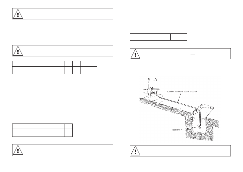
A foot valve must be used on the end of the suction pipe for below ground
installations or a check valve in the suction line for above ground water
sources (ie. tanks). For optimum pump operation and priming ensure that the
suction line is level or rises evenly from the water source to the pump.
Suction Piping
Polythene pipe is recommended for the pump suction as it provides flexibility, reduces the
transmission of pump noises and provides a convenient method of disconnecting the pump without
unions or the need to cut into the piping. For best performance situate the pump as close to the
water source as practical. To reduce pipe friction and maximise flow we recommend the following
Suction Pipe Sizes for the lengths indicated.
Suction Port size 1
1
/
2
” BSP
Suction Length
up to 10m
10m to 30m
Pipe size
40mm (1
1
/
2
”)
50mm (2”)
Use thread seal tape or pipe compound on all threaded pipe fittings or connections and ensure
they are leak free.
Suction piping should be laid so there is a constant rise from the water source to the pump.
Any high spots will cause air pockets to form and reduce the efficiency of the system as well as
creating priming difficulties.
Plumbing Details for ‘Shallow Well’ Installations
For Automatic Pressure System Installation.
NOTE: Suction leaks are the biggest cause of operating difficulties and are hard
to detect because the problem is air leaking into the pipe and there may be no
external sign of the leak.