2 initial setup, 3 pressure measurement sequence, 2 initial setup 2.3 pressure measurement sequence – Condec Source 3000 User Manual
Page 8
4
Source 3000 Operation and Maintenance Manual
2.2
Initial Setup
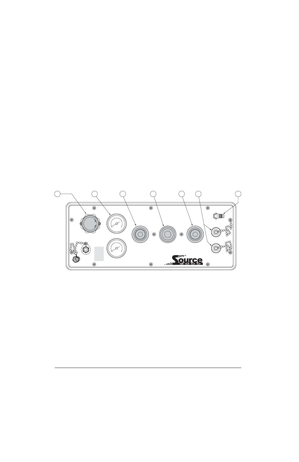
To prepare for actual calibration usage, see Figure 2-2 below and proceed as follows:
1. Check that the
COARSE ADJUSTMENT
valve (1) is closed (rotate clockwise until it stops) and that the
vent valve (2) is open (two turns counter-clockwise from its stop).
2. Using the
PRESSURE LIMIT CONTROL
regulator (5), adjust the maximum system input pressure, as read
by the pressure limit monitor (4), to any desired value higher (typically 20–50% higher) than the
full-scale range of the device under test. Using this technique, the device under test is fully protected
from being accidentally over-pressurized.
3. Connect the male quick disconnect end of the port hose supplied by customer to one of the port (6)
fittings. Use supplied 1/4 female NPT quick disconnect fitting, (PN 55394) between port hose and Port 1
or Port 2.
4. Connect the other end of the port hose to the input port of the electronic standard, using adapters if
required. Tighten all connections.
5. Connect the end of the test hose supplied by customer to the electronic standard output port and the other
end to the unit under test. Tighten all connections properly.
NOTE
: If using a tee type port/test hose
connection, the electronic standard is connected between the port and unit under test.
Figure 2-2. Initial Setup Procedure
2.3
Pressure Measurement Sequence
1. To apply pressure, close the
VENT
valve (2) approximately two turns until it stops, then open the
COARSE ADJUSTMENT
valve (1) approximately 1/2 turn counter-clockwise until the display begins to
move. The pressure may change rapidly until reaching approximately 90% of the desired final value.
2. Use either the
COARSE ADJUSTMENT
or
VENT
valve to obtain a specific pressure reading. Both provide
precise control. As the pressure approaches the desired value, the valve being used for control should be
rotated slowly clockwise to its closed position. With a little experience, pressure values very close to the
desired final value may be quickly achieved.
3. To obtain exact pressure readings, slowly rotate the
VERNIER
control (3) knob in the direction required
(clockwise to increase pressure) as indicated by the electronic standard display.
DECREASE
INCREASE
FILL PORT
MAX. 3000 PSI
NITROGEN ONLY
SUPPLY PRESSURE
PRESSURE LIMIT MONITOR
PRESSURE LIMIT CONTROL
COARSE ADJUSTMENT
VERNIER
VENT
VENT
PORT 2
PORT 1
6
7
2
3
1
4
5