STI AP-1-G-I User Manual
Page 5
- 5 -
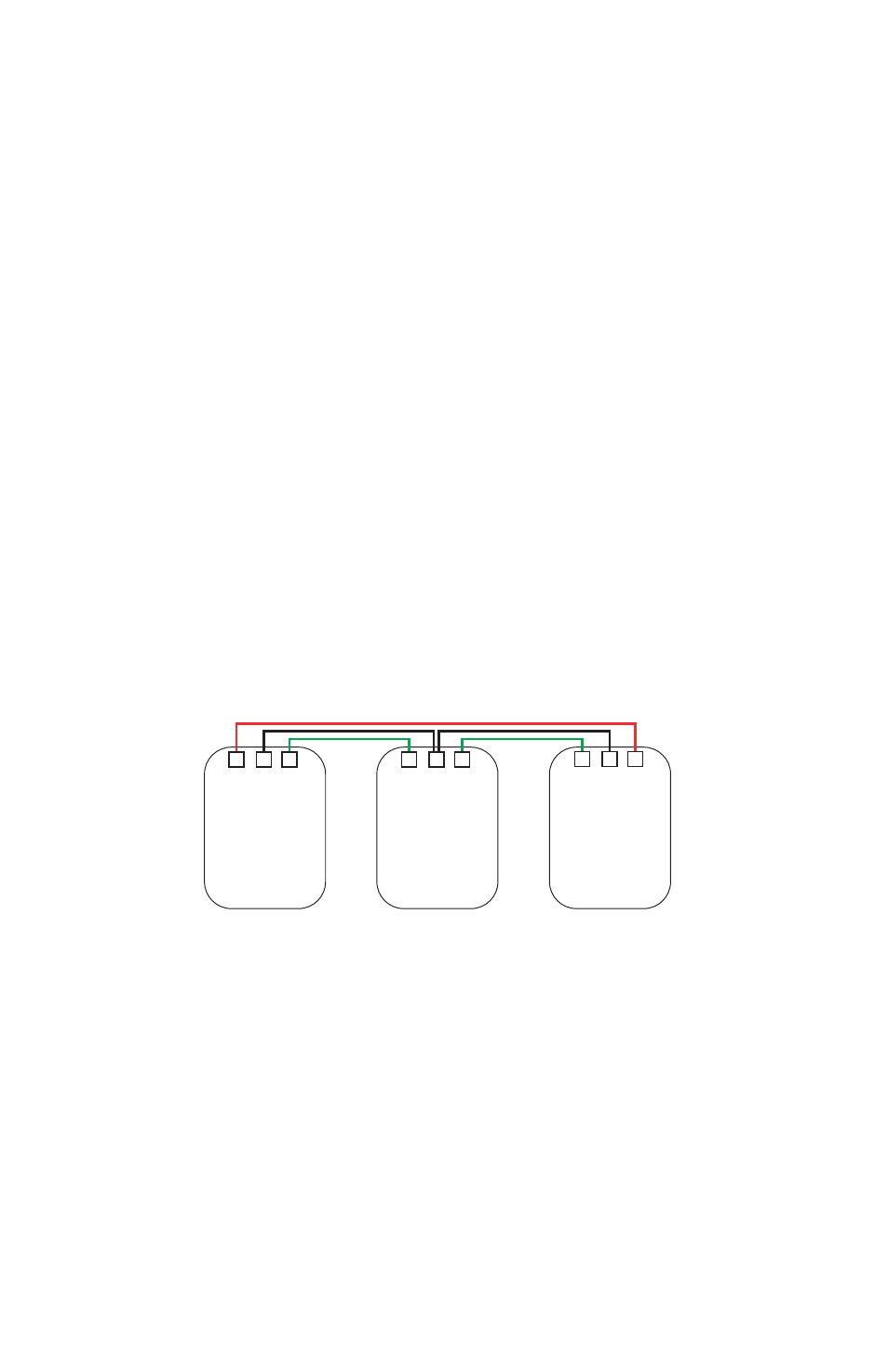
Networking 3 or more units (Diagram 2) front covers are removed
1. Be sure all units are switched “OFF” and front covers are removed.
2. DIP switch SW8 should be “ON” on all the units (each unit expects to be connected to another unit).
3. Connect the “Network COM” terminals by inserting a wire into unit #1, and linking this to the same
terminal on unit #2. Now do the same by connecting an additional wire to the “Network COM”
terminal on unit #2, and linking this to the same terminal on unit #3. Repeat this for subsequent
units until all units are linked.
4. Insert a wire into the “Network Out” terminal on unit #1, and link this to the “Network In” terminal on
unit #2. Now insert a wire into the “Network Out” terminal on unit #2 and link this to the “Network
In” terminal on unit #3. Repeat this step for each subsequent unit.
5. Important! On the final unit (e.g. unit #3) ensure that the “Network Out” terminal is linked back to the
“Network In” terminal on unit #1, creating a loop. (It is not necessary to do this step for the COM
wire.)
6. Turn all the units “ON” using the master key switch.
TEST
7.
Unit #1, depress the operating element. This will send the unit into alarm condition, causing
the activation flag to drop into view and the integral alarm to sound. Unit #2 & unit #3 will also
immediately trigger into alarm.
8. Resetting the networked units can only be done by manually resetting the originally activated unit
(showing the activation flag, in this case unit #1) using the reset key. This will return the other units
back into “standby” condition.
Netw
ork
IN
Netw
ork
CO
M
Netw
ork
OUT
Netw
ork
IN
Netw
ork
CO
M
Netw
ork
OUT
UNIT 2
UNIT 3
Diagram 2
Netw
ork
IN
Netw
ork
CO
M
Netw
ork
OUT
UNIT 1