Main unit disassembly process, Main unit disassembly flowchart – Acer 7715Z User Manual
Page 66
56
Chapter 3
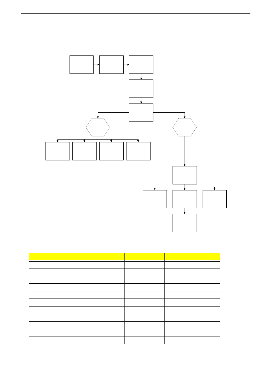
Main Unit Disassembly Process
Main Unit Disassembly Flowchart
Screw List
Step
Screw
Quantity
Part No.
LCD Module
M2.5*8
2
86.N2802.003
LCD Module
M2.5*8
4
86.N2802.003
Upper Cover
M2.5*8
11
86.N2802.003
Upper Cover
M2.5*8
9
86.N2802.003
Power Board
M2*3
2
86.N2802.006
Left Speaker Module
M2*3
1
86.N2802.006
Right Speaker Module
M2*3
1
86.N2802.006
TouchPad Bracket
M2*3
2
86.N2802.006
Mainboard
M2.5*4
1
86.N2802.001
Thermal Module
M1.98*3.0
4
86.N2802.004
CPU Fan
M2*3
3
86.N2802.006
Remove
Mainboard
Remove
Switch Cover
Remove
Keyboard
Remove
Upper Cover
Remove
LCD Module
Remove
Power Board
Remove External
Modules before
proceeding
Remove
TouchPad
Bracket
Upper
Cover
Lower
Cover
Remove
Left Speaker
Module
Remove
CPU
Remove
RTC Battery
Remove
Thermal Module
Remove
Right Speaker
Module
Remove
CPU Fan
This manual is related to the following products: