PULS UB20.241 User Manual
Page 4
UB20 Instruction Manual for DC UPS UB20.241
UB20 Bedienungsanleitung für die DC USV UB20.241
Terminals and Wiring
Wires between the DC-UPS and the batteries that are too small or too long can shorten the
buffer time or can result in a malfunction of the DC-UPS. Do not use wires smaller than 4mm
2
(or AWG 12) and not longer than 2x1.5m.
Use appropriate copper cables that are designed for a minimum operating temperature of:
60°C for ambient temperatures up to 45°C,
75°C for ambient temperatures up to 60°C and
90°C for ambient temperatures up to 70°C.
Follow national installation codes and regulations! Ensure that all strands of a stranded wire
enter the terminal connection!
Ferrules are allowed. Unused terminal must be closed.
Input/ Output/ Battery
Signals
Solid
wire
0.5-6mm
2
0.2-1.5mm
2
Stranded
wire
0.5-4mm
2
0.2-1.5mm
2
American wire gauge
AWG 20-10
AWG 22-14
Wire diameter (including ferrules)
max. 2.8mm
max. 1.5mm
Wire stripping length
7mm / 0.28inch
6mm / 0.25inch
Tightening torque
1Nm / 9lb.inch
0.4Nm / 3.5lb.inch
Anschlussklemmen und Verdrahtung
Zu dünne oder zu lange Kabel zwischen DC-USV und Batterie können die Pufferzeit verkürzen oder
zum Fehlverhalten der DC-USV führen. Benutzen Sie keine Anschlussdrähte kleiner als 4mm
2
(oder
AWG 12) und nicht länger als 2x1,5m.
Verwenden Sie geeignete Kupferkabel, die mindestens für:
60°C bei einer Umgebungstemperatur bis zu 45°C,
75°C bei einer Umgebungstemperatur bis zu 60°C und
90°C bei einer Umgebungstemperatur bis zu 70°C zugelassen sind.
Aderendhülsen sind erlaubt. Nationale Bestimmungen und Installationsvorschriften beachten!
Sicherstellen, dass keine einzelnen Drähte von Litzen abstehen. Nichtbenutzte Klemmen schließen.
Eingang/ Ausgang/ Batterie
Signale
Starrdraht
0,5-6mm
2
0,2-1,5mm
2
Litze
0,5-4mm
2
0,2-1,5mm
2
AWG
AWG 20-10
AWG 22-14
Drahtdurchmesser (inkl. Aderendhülsen)
max. 2,8mm
max. 1,5mm
Abisolierlänge
7mm / 0,28inch
6mm / 0,25inch
Anzugsdrehmoment
1Nm / 9lb.inch
0.4Nm / 3.5lb.inch
Isolation and Dielectric Strength
The relay contacts and the inhibit input are floating and separated from the input and output
voltage. The following isolation tests were performed:
Galvanische Trennung und Isolationsfestigkeit
Die Relaiskontakte und Inhibt Eingang haben keinen Bezug zur Eingangs- oder Ausgangsspannung.
Die folgenden Isolationstests wurden durchgeführt:
A B
C
Type Test (60s)
1060Vac
1060Vac 1060Vac
Factory Test (5s)
650Vac
650Vac
650Vac
Field Test (5s)
500Vac
500Vac
500Vac
Cut-off current setting
>90mA
>1mA
>1mA
In / Output
Battery
Chassis
Signal
Port
A
C
B
A B C
Typprüfung (60s)
1060Vac
1060Vac
1060Vac
Stückprüfung (5s)
650Vac
650Vac
650Vac
Wiederholungsprüfung (5s) 500Vac
500Vac
500Vac
Strom- Abschaltschwelle
>90mA
>1mA
>1mA
Ein/Ausgang
Batterie
Gehäuse
Signal-
anschlüsse
A
C
B
Type and factory tests are conducted by the manufacturer. Field tests may be conducted in the
field using the appropriate test equipment which applies the voltage with a slow ramp (2s up and
2s down). Connect all phase-terminals together as well as all output poles before the test is
conducted. When testing, set the cut-off current settings to the value in the table below.
Typ- und Stückprüfungen werden beim Hersteller durchgeführt. Wiederholungsprüfungen dürfen
mittels eines geeigneten Prüfgenerators mit langsam (2s) ansteigenden und abfallenden
Spannungsrampen in der Anwendung erfolgen. Vor den Tests sind alle Phasen wie auch alle
Ausgangspole miteinander zu verbinden. Während der Tests darf die Strom- Abschaltschwelle nicht
kleiner als der in der Liste angegebene Wert sein.
LED Indicators and Troubleshooting
LED Anzeigen und Fehlersuche
1
0
Ready
1
0
Charging
1
0
Buffering
10
Hz
Green Status LEDs
Each battery has an own Status LED. The signals are the same
for both batteries.
- The LEDs are on solid when the battery is charged (> 85%), no
wiring failure is recognized, input voltage is sufficient and
inhibit signal is not active.
- The LEDs are flashing with a low frequency when the batteries
are charging and the state of charge is below 85%.
- The LEDs are flashing with a high frequency when the unit is in
buffer mode.
Grüne „Status“ LEDs
Jede Batterie besitzt eine eigene Statusanzeige. Die Signalisierung ist
für beide Anzeigen identisch.
- Die LEDs leuchten dauerhaft, wenn die Batterie > 85% geladen ist,
kein Verdrahtungsfehler vorliegt, die Eingangsspannung im
spezifizierten Bereich liegt und der „Inhibit“ Eingang nicht aktiv ist.
- Die LEDs blinken langsam, wenn die Batterie geladen wird und der
Ladezustand kleiner 85% ist.
- Die LEDs blinken schnell, wenn das Gerät sich im Pufferbetrieb
befindet.
1
0
Overload
1
0
Replace
Battery
1
0
Buffertime
expired
1
0
Inhibit
active
5
Hz
Yellow Diagnosis LED
- The LED is on solid when the output current is permanently
above 20A in buffer mode or 25A in normal mode.
- The LED is flashing with a low frequency when one battery has
failed the periodically performed battery quality test. The
battery that has failed is indicated by the green LED which is
off. The battery should be replaced as soon as possible.
- The LED is double flashing when the output has switched off
due to setting of the Buffer-time limiter. This signal will be
displayed for 15 minutes.
- The LED is flashing with a high frequency when buffering is
disabled due to an active inhibit signal.
Gelbe “Diagnosis” LED
- Die LED leuchtet dauerhaft, wenn der Ausgangsstrom im Pufferbetrieb
20A oder im Normalbetrieb 25A dauerhaft überschreitet.
- Die LED blinkt langsam, wenn eine Batterie die regelmäßig
stattfindende Batterieüberprüfung nicht bestanden hat. Welche der
beiden Batterien betroffen ist, erkennt man an der grünen LED, die
dann aus ist. Die Batterie sollte baldmöglichst ersetzt werden.
- Ein Doppelblinken zeigt an, dass der Ausgang abgeschaltet hat, weil
die eingestellte maximale Pufferzeit abgelaufenen ist. Die Meldung
wird 15 Minuten lang angezeigt.
- Die LED blinkt schnell, wenn ein aktives „Inhibit“ Signal eine Pufferung
verhindert.
1
0
Check
Wiring
1
0
Input
Voltage
1
0
Temp.
Red Error LED
This LED indicates that charging or buffering is not possible.
- The LED is on solid when a failure in the wiring, battery or
battery fuse is identified.
- A single flash indicates that the input voltage is >30V or the
input voltage is too low for the adjusted buffer voltage.
- A double flash indicates that the temperature of the DC-UPS is
too high (> 70°C) or that the temperature of the battery is too
high (> 50°C) or too low (< -10°C in setting <10Ah).
Rote “Error” LED
Diese LED zeigt an, dass ein Laden oder Puffern nicht möglich ist.
- Die LED leuchtet dauerhaft, wenn ein gravierender Fehler in der
Batterie, Batterieverdrahtung oder Batteriesicherung erkannt wurde.
- Ein Blinken zeigt an, dass die Eingangsspannung >30V ist oder die
Eingangsspannung für die gewählte Pufferspannung zu klein ist.
- Ein Doppelblinken zeigt an, dass die Temperatur der DC-USV zu hoch
ist (> 70°C) oder dass die Temperatur der Batterien zu hoch ist
(>50°C) oder zu niedrig ist (<-10°C bei Stellung <10Ah).
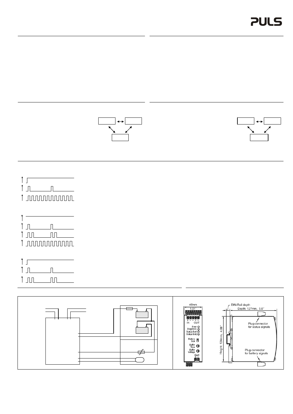
Wiring Scheme / Verdrahtungsplan Dimension
/
Abmessung
Battery
Temp. Sensor
+
-
Output
Input
+
-
Fuse
+
-
BAT1
12V
+
-
BAT2
12V
(+)
(-)
Temp.
Sensor
Center-Tap
Temp.
Sensor
Auto
Resettable
Fuse
PT1000
Center-Tap
Load
Power
Supply
+
-
(13)
(12)
(11)
DC-UPS
PU-392.010.00-10F
The information in this document is believed to be accurate and reliable and may change without notice.