Unit connectors, 10 pin i/o terminal connector block – Axis Communications 223M User Manual
Page 11
AXIS 221/223M Installation Guide
Page 11
ENGLISH ENGLISH ENGL
ISH
Unit connectors
Network connector - RJ-45 Ethernet connector. Supports Power over Ethernet. Using
shielded cables is recommended.
Power connector - Mini DC connector. 5.1V DC, max 3.6W. See product label for
±
connection.
Audio in - 3.5mm input for a mono microphone, or a line-in mono signal (left channel is
used from a stereo signal).
Audio out - Audio output (line level) that can be connected to a public address (PA) system
or an active speaker with a built-in amplifier. A pair of headphones can also be attached. A
stereo connector must be used for the audio out.
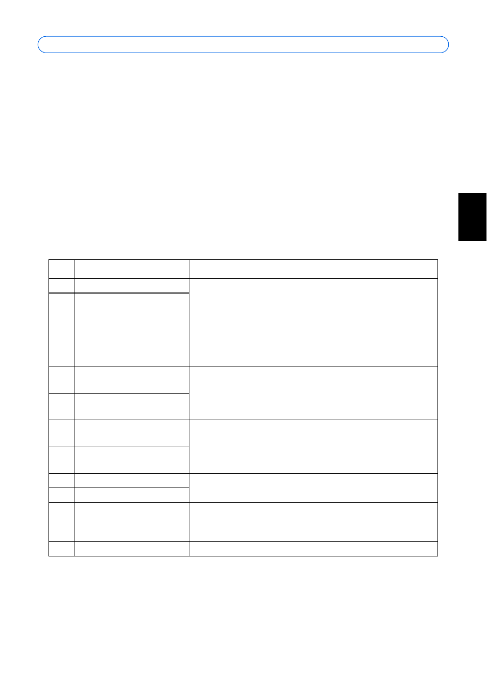
10 pin I/O terminal connector block
Pin Function
Description
1
Output A
On the external device output terminals (A and B), there is
no distinction between positive and negative (+ and -). The
terminals use a photocoupler and are electrically isolated
from the other internal circuitry.
The maximum load should not exceed 100mA and the max-
imum voltage should be not more than 50V DC. Note: Con-
necting AC to the output will damage the unit.
2
Output B
3
Digital Input 1
Photocoupler Anode (+)
Photocoupled Input 1. Electrically isolated from the chassis
and connectors, this input can be supplied from an external
DC voltage or the DC Power Input/Output on pins 9 (DC+)
and 10 (GND).
4
Digital Input 1
Photocoupler Cathode (-)
5
Digital Input 2
Photocoupler Anode (+)
Photocoupled Input 2. As above.
6
Digital Input 2
Photocoupler Cathode (-)
7
RS-485-A (non-inverting)
A half-duplex RS-485 interface for controlling auxiliary
equipment.
8
RS-485-B (inverting)
9
DC+ Power Output
This can drive the photocoupler inputs or other equipment.
The output voltage level is 3.0 V. A maximum current of
100mA can be sourced from the DC output.
10
GND
Ground