Installation (continued) – Sterling SF User Manual
Page 7
7
INSTALLATION (continued)
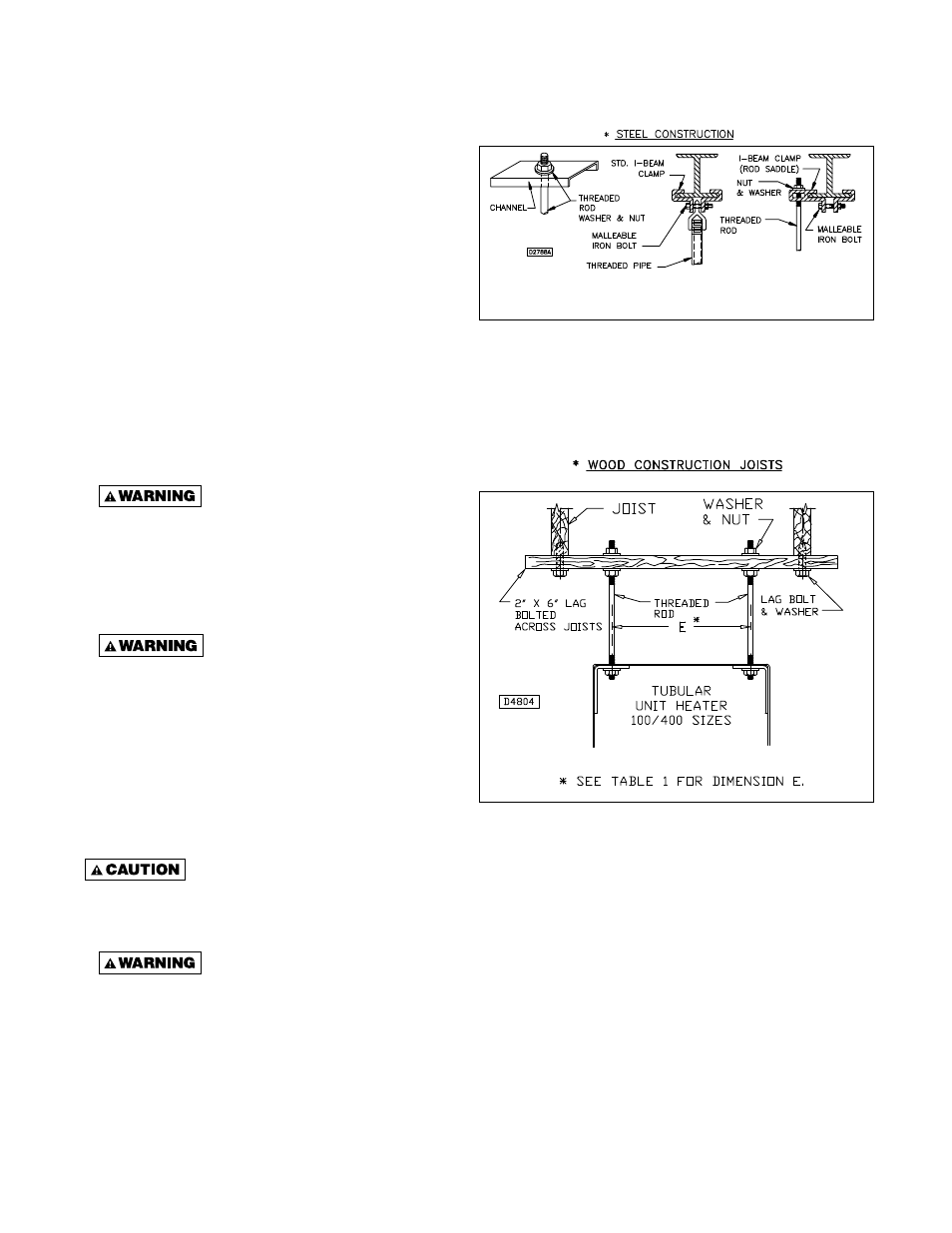
Figure 3A - Heater Mounting*
*All hanging hardware and wood is not included with the unit (To
be fi eld supplied).
Note: Threaded rod is 3/8".
Figure 3B - Heater Suspension
Note: Threaded rod is 3/8".
CLEARANCES: Each Gas Unit Heater shall be
located with respect to building construction and
other equipment so as to permit access to the Unit
Heater. Clearance between ver tical walls and the
vertical sides of the Unit Heater shall be no less than
6 in. (152mm). To ensure access to the control box, a
minimum of 18 in. (457mm) is required for the control
box side. A minimum clearance of 6 in. (152mm) must
be maintained between the top of the Unit Heater and
the ceiling. The bottom of the Unit Heater must be no
less than 12 in. (305mm) from any combustible. The
distance between rear of unit and vertical wall should
be no less than 18 in. to maintain inlet air flow. The
distance between the fl ue collector and any combustible
must be no less than 6 in. (152mm). Also see AIR FOR
COMBUSTION and VENTING sections.
NOTICE: Increasing the clearance distances may
be necessary if there is a possibility of distortion or
discoloration of adjacent materials.
Make certain that the lifting
methods used to lift the heater and the method
of suspension used in the fi eld installation of the
heater are capable of uniformly supporting the
weight of the heater at all times. Failure to heed
this warning may result in property damage or
personal injury!
Make sure that the structure
to which the unit heater is to be mounted is
capable of safely supporting its weight. Under
no circumstances must the gas lines, the venting
system or the electrical conduit be used to
support the heater; or should any other objects
(i.e. ladder, person) lean against the heater gas
lines, venting system or the electrical conduit
for support. Failure to heed these warnings may
result in property damage, personal injury, or
death.
Unit Heaters must be hung level
from side to side and from front to back, see Figure
3A and 3B. Failure to do so will result in poor
performance and/or premature failure of the unit.
Ensure that all hardware used in
the suspension of each unit heater is more than
adequate for the job. Failure to do so may result
in extensive property damage, severe personal
injury, or death!
Refer to Figures 3A and 3B for suspension of units.