Horizontally vented unit heaters (category iii), Venting (continued) – Sterling TC User Manual
Page 18
18
HORIZONTALLY VENTED UNIT HEATERS
(CATEGORY III)
Horizontal venting arrangements are designed to be used
with single wall vent pipe. Horizontal venting arrangements
must terminate external to the building using UL 1738
Listed single wall or double wall vent. For installations in
Canada, use corrosion resistant and gas-tight, listed vent
pipe conforming with local building codes, or in the absence
of local building codes, with current CSA-B149.1, Installation
Codes for Natural Gas Burning Appliances and Equipment
or CSA-B149.2, Installation Codes for Propane Gas
Burning Appliances and Equipment. See Figures 8, 9A and
10A for special installation requirements regarding these
venting conditions.
Do not use Type B (double wall)
vent internally within the building on horizontally
vented power vented units! This can result in
death, serious injury or substantial property
damage.
If double wall venting is used, components which are UL
Listed and approved for Category III positive pressure
venting systems MUST be used.
A Breidert Type L, Fields Starkap, or equivalent vent cap
must be supplied by the customer for each power vented
unit. The vent pipe diameter MUST be as specified in
Table 1. All unit sizes are factory equipped with the
required fl ue size collar; attach in place (if not mounted
to outlet); refer to included vent collar instruction sheet
for additional requirements.
Table 7
The vent terminal must be at least 12" (305mm) from
the exterior of the wall that it passes through to prevent
degradation of the building material by fl ue gases.
Through the wall vent for these appliances shall NOT
terminate over public walkways, or over an area where
the condensate or vapor could create a nuisance or
hazard or could be detrimental to the operation of
regulators, relief valves, or other equipment.
The vent pipe equivalent length must not exceed 50'
(15.2m). Equivalent length is the total length of straight
sections PLUS 10' (3.05m) for each 90° elbow and
4' (1.22m) for each 45° elbow.
Maintain clearance between the vent pipe and com-
bustible materials according to vent pipe manufacturers
instructions
Seal all vent pipe joints and seams to prevent leakage.
Use General Electric RTV-108, Dow-Corning RTV-732
silicone sealant or equivalent sealant with a temperature
rating of 500° F; or 3M #425 aluminum foil tape (or
equivalent). The vent air system must be installed to
prevent collection of condensate. Pitch horizontal pipes
downward 1/4" per foot (21mm per meter) toward the
outlet for condensate drainage.
Horizontal portions of the venting systems shall be
supported at maximum intervals of 4' (1.2m) to prevent
sagging (in Canada, suppor t at 3' (1m) maximum
intervals).
Insulate single wall vent pipe exposed to cold air or
running through unheated areas.
Each unit must have an individual vent pipe and vent
terminal! Each unit MUST NOT be connected to other
vent systems or to a chimney.
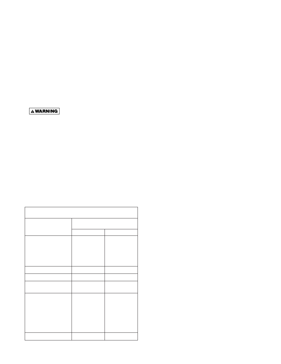
VENTING (continued)
Vent Systems
Termination Clearance Requirements
Structure/Object
Minimum Clearance
for Termination Locations
USA
CANADA
Door, window, or gravity vent
inlet; combustion air inlet for
other appliances
9 inch for 10,000 to
50,000 BTU/Hr
input; 12 inch for
input exceeding
50,000 BTU/Hr.
9 inch (230mm) for
10,000 to 50,000
BTU/Hr input;
12 inch (305mm)
for input exceeding
50,000 BTU/Hr.
Forced air inlet within 10 feet
3 feet above
6 feet (1.8m)
Adjoining Building or parapet
6 feet
6 feet (1.8m)
Adjacent public walkways
7 feet above
grade
7 feet (2.1m) above
grade
Electric, gas meters
& regulators
4 feet horizontal
3 feet (0.9m)
horizontally from
meter/regulator
asembly. 6 feet
(1.8m), any
direction, from
a gas service
regulator vent outlet
Above grade level*
1 foot*
1 foot (0.3m)*
*Above maximum anticipated snow depth.