List of parameters, Maintenance, calibration apparatus – Yokogawa JUXTA FT5V Thermocouple Converter (Free Range Type) User Manual
Page 4: 2 calibration procedure
4
IM 77J08T05-01E 1st Edition
2007.01.15-00
5. LIST OF PARAMETERS
Parameter Display
Items
A
DISPLAY
Display
A01
INPUT
Input value
A02
OUTPUT
Output value
A03
STATUS
Status (*1)
A04
REV NO
Revision number.
B
SET
Setting
B01
TAG NO.1
Tag number 1
B02
TAG NO.2
Tag number 2
B03
COMMENT1
Comment 1
B04
COMMENT2
Comment 2
B06
TYPE
Input type
B09
UNIT
Unit
B10
ZERO
Zero (0% of input range)
B11
SPAN
Span (Input span)
B12
BURN OUT
Burnout
C
ADJUST
Adjustment
C01 OUT 0%
Output 0% adjustment
C02 OUT 100%
Output 100% adjustment
C03 WIRING R
Wire resistance compensation
C04 ZERO ADJ
Input zero adjustment
C05 SPAN ADJ
Input span adjustment
C08 RJC
RJC on/off (*2)
*1:
This “STATUS” is for the customer’s engineer to check the history.
*2:
The RJC returns to ON after the power is turned off and then on again.
6. MAINTENANCE
The product starts running immediately when the power is turned
on; however, it needs 10 to 15 minutes of warm-up before it
meets the specified performance.
6. Calibration Apparatus
A voltage current source (Yokogawa 7651 or equivalent)
A digital multimeter (Yokogawa 7561 or equivalent)
A precision resistor of 250 Ω ±0.01%, 1W
A setting tool for adjustment (Refer to "4. Setting Parameters"
in this manual.
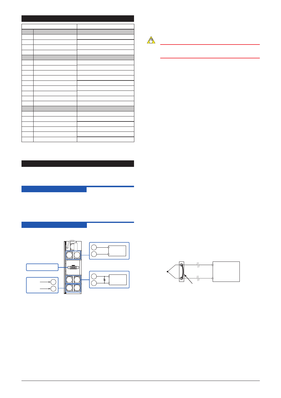
6.2 Calibration Procedure
1. Connect the instruments as shown below.
1
2
3
4
5
6
7
3
2
3
6
7
4
5
+
−
+
−
24V DC
+
−
Ro
DMM
Voltage
current
source
Input
Output
Ro: 250Ω precision resistor for
current output
Setting tool
Power supply
2. Turn off the RJC using the setting tool.
3. Use the voltage current source and apply the electromotive
force equivalent to 0, 25, 50, 75, and 100% of the measuring
range to the converter.
4. Verify that the corresponding output voltages are 0, 25, 50, 75,
and 100% respectively and within the specified accuracy rating.
(R
o
is used for current output.)
Use the setting tool (VJ77 Parameter Setting Tool or JHT200
Handy Terminal) to adjust the input/output signals.
Turning the RJC on/off
(1)
Read the parameter
[C08: RJC].
(2)
Select "ON" or "OFF" in the parameter
[C08: RJC].
NOTE
The RJC returns to "ON" after the power is turned off
and then on again.
Input Adjustment Procedure
(1)
Input the value equivalent to 0% value of the input range
to the converter.
(2)
Read the parameter
[C04: ZERO ADJ] and check the
input value.
(3)
Select “INC” or “DEC” in the parameter
[C04: ZERO
ADJ] to adjust.
INC: Increase (Adjusts the increased value of the input
[voltage] value)
DEC: Decrease (Adjusts the decreased value of the
input [voltage] value)
RST: Reset of the adjustment value
(4)
Input the value equivalent to 100% value of the input
range to the converter.
(5)
Read the parameter
[C05: SPAN ADJ] and check the
input value.
(6)
Adjust the span in the same way as (3).
Output Adjustment Procedure
When adjusting 0% value of output:
(1) Set the adjustment value 0% in the parameter
[C0:
OUT 0%].
•The value equivalent to 0% of the output range will be
output, irrespective of the input.
(2) Check the output value via digital multimeter, and adjust
it in the parameter
[C0: OUT 0%].
•If it slips out to the (+) side, set (−) value equivalent
to slipout; if it slips out to the (−) side, set (+) value
equivalent to slipout for adjusting the output value to
0%.
*: The 100% value of output can be adjusted by the same
operation as the above in
[C02: OUT 00%].
Wire Resistance Compensation
(1)
Short-circuit at the sensing end of the field side.
FT5A
FT5V
Short-circuit at the cable end
(2)
Read the parameter
[C04: ZERO ADJ] and make sure
the setting is "RESET".
(If the setting is "EXECUTE, select "RESET". The
compensation value will be reset.)
(3)
If "EXECUTE" is selected in the parameter
[C03:
WIRING R], the wire resistance compensation will be
done automatically.
For adjustment using a setting tool, refer to the User’s Manual for
each setting tool and “5. List of Parameters” in this manual.
User’s Manual for VJ77 [Document No.: IM 77J01J77-01E];
however, use the VJ77 of version R1.05 or later.
User’s Manual for JHT200 [Document No.: IM JF81-02E]