Setting parameters – Yokogawa JUXTA FT5V Thermocouple Converter (Free Range Type) User Manual
Page 3
3
IM 77J08T05-01E 1st Edition
2007.01.15-00
M4 screw terminals are provided for the connection of external
signals. Attach a crimp-on lug to each wire for connection to the
terminals.
●Recommended cables: A nominal cross-sectional area of 0.5
mm
2
or thicker for signal cables, and that of 1.25 mm
2
or thicker
for power cables.
Wiring Diagram
1
2
4
5
6
7
3
6
7
4
5
RJC
+
−
Input(RJC)
Output
Power supply
+
+
−
−
2
3
DO NOT use the terminal
NOTE
●The power line and input/output signal lines should
be installed away from noise-generating sources.
Otherwise accuracy cannot be guaranteed.
●Adhere strictly to the specifications to avoid
overheating or damage. Before turning on the power,
ensure the following:
(a) Power supply voltage and input signal value
applied to the product should meet the required
specifications.
(b) The external wiring to the terminals and wiring to
ground are as specifications.
●Do not operate the product in the presence of
flammable or explosive gases or vapors.
●The product is sensitive to static electricity; exercise
care when in operation. Before you operate the
product, touch a nearby metal part to discharge
static electricity.
●Connect the RJC sensor to the terminal of the
converter together with the input signal line so that
the crimp-on lug of the input signal line overlaps the
RJC sensor.
●Handle the RJC sensor lead wire with care to prevent
disconnection.
Power Supply and Isolation
Power supply voltage: 24V DC ±10% (ripple: less than 5% p-p)
Current consumption: FT5A 65mA, FT5V 50mA
Insulation resistance: 100MΩ at 500V DC between input, output
and power supply mutually
Withstand voltage: 1500V AC/minute between input-output,
input-power supply
500V AC/minute between output-power supply
4. SETTING PARAMETERS
The parameters are set as you specified in your order. Refer
to the following to change the default settings.
Set the parameters using a PC (VJ77 Parameter Setting Tool)
or the Handy Terminal. Refer to "5. List of Parameters" in this
manual and the User’s Manual for VJ77 PC-based Parameters
Setting Tool (IM 77J01J77-01E) or the User’s Manual for JHT200
Handy Terminal (IM JF81-02E). Parameters are shown in
brackets "[ ]".
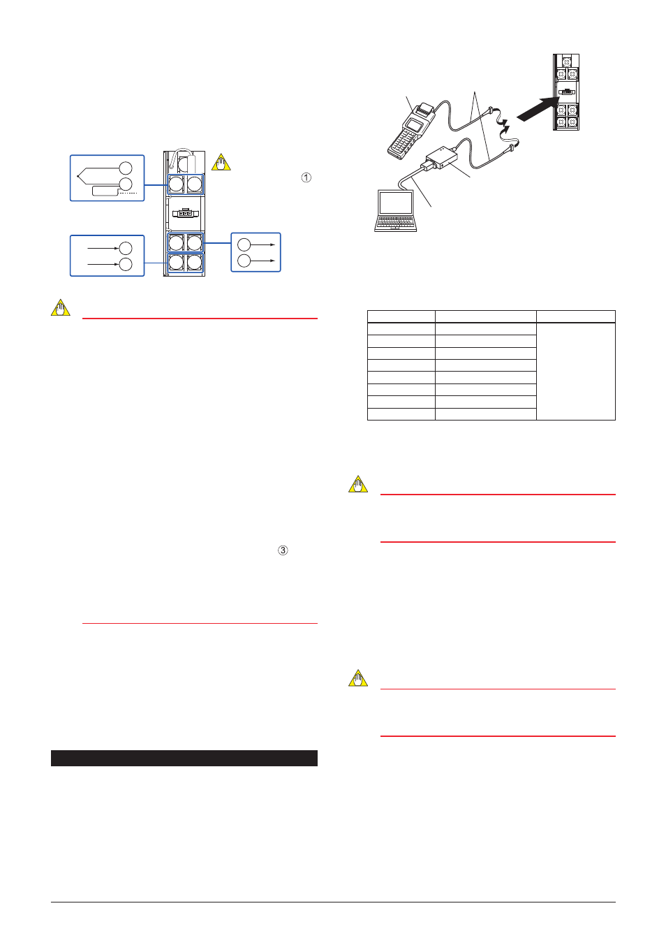
Connection of Setting Tools
VJ77 Dedicated adapter (E9789HA)
[Provided with VJ77]
PC with VJ77 installed
Dedicated cable (E9786WK)
[Provided with VJ77]
*Be sure to use the VJ77 of version R1.05 or later.
JHT200
Handy Terminal
JUXTA communication cable
3 pin connector (F9182ED)
[Provided with VJ77 and JHT200]
Setting Thermocouple Type
Set the thermocouple type to be connected to the input in
[B06: TYPE].
Display
Measuring range
Measuring span
K TYPE
-270 to 1372°C
3mV or more
E TYPE
-270 to 1000°C
J TYPE
-210 to 1200°C
T TYPE
-270 to 400°C
R TYPE
-50 to 1768°C
S TYPE
-50 to 1768°C
B TYPE
0 to 1820°C
N TYPE
-270 to 1300°C
Setting Temperature Unit
Set the temperature unit of the input range in
[B09: UNIT].
NOTE
Do not set the "-----" as the temperature unit, even if it
is displayed during the setting.
Otherwise it may cause the malfunction or damage.
Setting Input Range
Set the zero percent value of input range in
[B0: ZERO], and
the span of input range in
[B: SPAN].
Setting Burnout Action
Set the burnout action in
[B2: BURN OUT].
Set "OFF", "UP", or "DOWN."
NOTE
The wire resistance compensation should be applied
when the setting of input range, burnout action
direction or input wiring has been changed.