Yokogawa JUXTA M Series Digital Limit Alarms MVTK User Manual
Page 8
IM 77J04T31-01E 2nd Edition Feb. 09, 2007-00
8
14. MAIN SPECIFICATIONS
■
Model and Suffix Codes
- 0 0 - /
Digital Limit Alarm (Thermocouple Input Type)
General use type
Always 0
24 V DC
±
10%
100-240 V AC/DC (Operating range: 85 to 264 V AC/DC)
Thermocouple input
Custom order
Alarm output (transfer contact [1a1b] ), 2 points
Alarm output (NO contact), 4 points
1 to 5 V DC
4 to 20 mA DC
Communication function (RS-485)
No monitor output
UP
DOWN
OFF (No burnout)
Without socket
Model
MVTK
Suffix Codes
Type
Power Supply
Input Signal
Output Signal
Monitor Output
Burnout
Optional Specification
3
6
1
2
6
A
P
N
U
D
N
-U
-Z
0
/SN
-0
Description
■
Input and Display
Number of inputs: 1 point
Input signal: Set the measured input range within the instrument input range. (Refer to Section 7.1.)
Input resistance: 1 M
Ω
(4 k
Ω
during power off)
Allowable leadwire resistance: 500
Ω
or less
However, when used with BARD, this value can be added to the BARD internal resistance.
Maximum allowable input:
±
4 V DC
PV (measured value) display: 4-digit, 7-segment, red/green LED, character height of 13.5 mm
Data display: 4-digit, 7-segment, green LED, character height of 9 mm
Alarm indicator lamp: 2 orange LEDs for 2 points of alarms or 4 orange LEDs for 4 points of alarms.
Lights up if an alarm occurs.
Economical mode: Turns off the indicating LED if no keystroke is made within the set time.
Setting range: 0 (does not go off) or 1 to 60 minutes
Active color PV display (PV display color changing function): This function changes the PV display
color from green to red or from red to green according to the set PV display color
mode shown below.
[PV display color mode to be set]
Link to alarm 1: Links to alarm 1.
Link to alarm 1 and alarm 2: Links to alarm 1 and alarm 2.
Link to alarm 1 to alarm 4 (only for 4 points of alarms): Links to alarm 1 to alarm 4.
SP deviation: Changes the PV display color according to whether measured value is less than
SP deviation high limit or SP deviation high limit or more; whether measured value is
more than SP deviation low limit or SP deviation low limit or less.
PV limit: Changes the PV display color according to whether measured value is less than
measured range high limit or measured range high limit or more; whether measured
value is more than measured range low limit or measured range low limit or less.
Fixed color: Fixes PV display color in green or red.
■
Output
Signal type: Relay contact
Number of outputs: 2 points of contact outputs (transfer contact [1a1b] ) or 4 points of contact
outputs (NO contact)
Contact rating: 120 V AC/1 A, 220 V AC/0.5 A (resistance load)
30 V DC/1 A, 120 V DC/0.1 A (resistance load)
Alarm action:
PV high-limit alarm
PV low-limit alarm
Deviation high-limit alarm
Deviation low-limit alarm
Deviation high and low-limit alarm
Deviation within high and low-limit alarm
Energized or de-energized under normal condition
Energized or de-energized under normal condition
Energized or de-energized under normal condition
Energized or de-energized under normal condition
De-energized under normal condition
De-energized under normal condition
Alarm action
Relay action
Alarm setting range: Within the input range
Setting resolution: 1 digit
(Note)
Setpoint setting: Virtual setpoint when the deviation alarm occurs
Setting range: Within the input range
Setting resolution: 1 digit
(Note)
Hysteresis setting range: The value resulting from adding a hysteresis value to an alarm setpoint
should be within the set input range.
Setting resolution: 1 digit
(Note)
Note: The content of 1 digit is variable according to the set range code No.
Alarm ON delay setting: Condition monitoring time from the establishment of alarm conditions to its
output
Setting range: 0 to 999 seconds
Setting resolution: 1 second (However, about 0.2 second is to be added to the set time to prevent
wrong operation.)
Alarm OFF delay setting: Condition monitoring time from the establishment of return-to-normal
conditions to its output
Setting range: 0 to 999 seconds
Setting resolution: 1 second (However, about 0.2 second is to be added to the set time to prevent
wrong operation.)
■
Monitor Output
●
Analog Output
Output signal: 1 to 5 V DC or 4 to 20 mA DC
Allowable load resistance: 2 k
Ω
or more for 1 to 5 V DC
350
Ω
or less for 4 to 20 mA DC
Output variable range: -6 to +106%
Output scaling: Set any value within the measured input range. (Set the value so that the input
range corresponding to the output scaling converted into thermoelectromotive force is
3 mV or more.)
Output accuracy:
±
0.1% of output span
However, the accuracy is limited in the following cases according to the output scaling
setting.
When the input range corresponding to the output scaling converted into thermoelectromotive force
is less than 27.5 mV
in the instrument input range M:
Accuracy=
±
0.1 (%)
ϫ
27.5 (mV)
Input range converted into thermoelectromotive force (mV)
(%)
When the input range corresponding to the output scaling converted into thermoelectromotive
force is less than 10 mV
in the instrument input range L :
Accuracy=
±
0.1 (%)
ϫ
10 (mV)
Input range converted into thermoelectromotive force (mV)
(%)
●
Communication Output (RS-485)
The MVTK can be connected to a personal computer, graphic panel, Yokogawa’s programmable
controller FA-M3 or programmable controllers of other manufacturers.
Standards: EIA RS-485
Maximum number of connectable units: 31 units
Maximum communication distance: 1200 m
Communication method: 2-wire half duplex, start-stop synchronization, non-procedural
Baud rate: 1200, 2400, 4800 or 9600 bps
Data length: 8 or 7 bits
Stop bit: 1 or 2 bits
Parity: Even, odd or none
Communication protocol: PC link, PC link with SUM, MODBUS ASCII, MODBUS RTU or Ladder
PC link communication: Communication protocol with a personal computer, graphic panel or UT
link module of FA-M3
MODBUS communication: Communication protocol with a personal computer
(SCADA).
Ladder communication: Communication protocol with ladder communication module of FA-M3
and programmable controller of other manufacturers.
■
Standard Performance
Input display accuracy:
±
0.1%
±
1 digit of instrument input range span
Alarm action point setting accuracy:
±
0.1%
±
1 digit of instrument input range span
Reference junction compensation accuracy:
±
1
°
C (other than Type R and S),
±
2
°
C (Type R and S)
at 25
°
C
±
15
°
C
Response speed: 500 ms (Time to alarm output when the input change is 10 to 90% and alarm
setpoint is 50%. When the alarm delay setting and hysteresis are minimum.)
Burnout: UP, DOWN or OFF
Burnout time: 60 seconds or less
Action: High-limit alarm output for UP, Low-limit alarm output for DOWN
Insulation resistance: 100 M
Ω
/500 V DC between inputs, alarm outputs, power supply and monitor
output mutually.
Withstand voltage: 2000 V AC/minute between inputs, (alarm outputs 1, 2, 3 and 4), monitor
output and power supply mutually.
However, the following is excluded.
1000 V AC/minute between (alarm outputs 1 and 4) and (alarm outputs 2 and 3) and
between inputs and monitor output.
(For 2 points of alarms, alarm outputs 3 and 4 are excluded.)
Power supply voltage: 24 V DC
±
10%, 100-240 V AC/DC (-15%, +10%) 50/60Hz
Power consumption: 24 V DC 2.7 W, 110 V DC 2.5 W, 100 V AC 4.2 VA,
200 V AC 5.4 VA
Effect of power supply fluctuation:
±
0.1% of span or less for the fluctuations within the allowable
range of each power supply specification
Effect of ambient temperature change:
±
0.2% of span or less for a temperature change of 10
°
C
Effect of leadwire resistance change:
±
15
V or less for a change of 100
Ω
■
Mounting, Appearance and Environmental Conditions
Construction: Plug-in type
Material:
Casing; ABS resin (black), UL94 V-0
Socket; Modified polyphenylene oxide resin, including glass fiber (black),
UL94-V1
Mounting method: Wall or DIN rail mounting
Connection method: M3.5 screw terminal for input/output and power supply
3-pin 2-piece connector for monitor output
External dimensions: 51 (W)
ϫ
86.5 (H)
ϫ
133 (D) mm (including a socket)
Weight:
Main unit; approx. 270 g
Socket; approx. 80 g
Operating temperature range: 0 to 50
°
C
Operating humidity range: 5 to 90% RH (no condensation)
Operating conditions: Avoid installation in such environments as corrosive gas like sulfide hydrogen,
dust, sea breeze and direct sunlight.
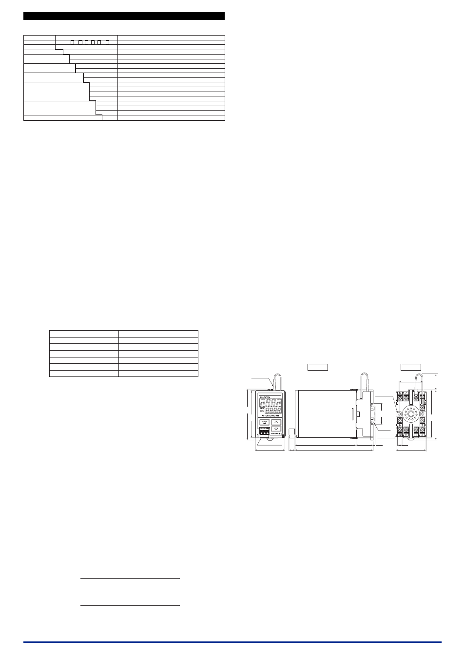
■
External Dimensions
103
133
50
30
7.8
40
10
86.5
80
(20)
85
(35.4)
81
(3.3)
*1 To be added when the monitor output is specified.
Monitor output
terminal *1
2-Ø4.5
Mounting hole
(depth: 24.5)
Main unit
Socket
51 max.
RJC sensor
11-M3.5
ϫ
7
screw
DIN rail
Unit: mm