Yokogawa JUXTA M Series Digital Limit Alarms MVTK User Manual
User’s manual, Important, Warning
User’s
Manual
Network Solutions Business Divisiion
2-9-32, Naka-cho Musashino-shi, Tokyo 180-8750 Japan
Phone: +81-422-52-7179
Facsimile: +81-422-52-6619
1
1. NOTICE
This user’s manual should be carefully read before installing and operating the product.
The following symbol is used on the product and in this manual to ensure safe use.
This symbol is displayed on the product when it is necessary to refer to the user’s manual for
information on personnel and instrument safety. This symbol is displayed in the user’s
manual to indicate precautions for avoiding danger to the operator, such as an electric shock.
The following symbols are used only in this manual.
IMPORTANT
Indicates that operating the hardware or software in a particular manner may cause
damage or result in a system failure.
NOTE
Draws attention to essential information for understanding the operations and/or
functions of the product.
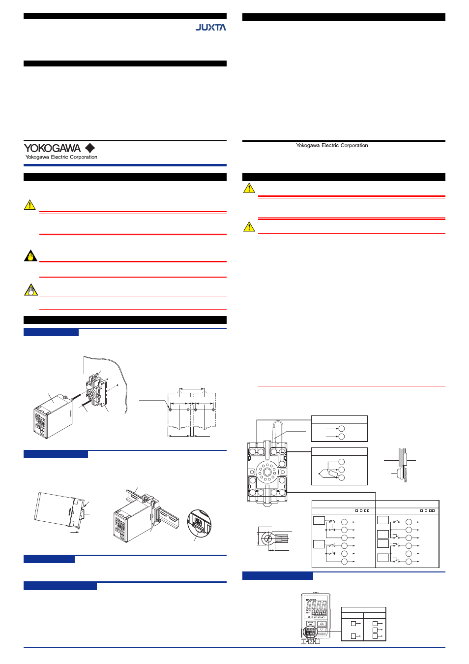
2. MOUNTING METHODS
2.1
Wall Mounting
Unfasten the upper and lower stoppers to disconnect the main unit from the socket. Next, anchor
the socket onto the wall with two M4 screws. Then plug the main unit into the socket and secure the
main unit with the upper and lower stoppers.
(51)
40
±
0.2 (16) 40
±
0.2
Pitch: 56 or more
(5 or more)
2-ø4.5 or 2-M4
•
Mounting Dimensions
Unit: mm
Socket
Stopper
Main unit
Mounting
screw
Note:
• For side-by-side mounting, provide spacing of 5 mm or
more between the products.
• For DIN rail mounting, use the supplied spacer to
provide spacing of 5 mm between the products.
2.2
DIN Rail Mounting
Locate the MVTK so that the DIN rail fits into the upper part of the DIN-rail groove at the rear of the
socket, and fasten the socket using the slide lock at the lower part of the socket. For side-by-side
mounting, attach the spacer supplied with the product to the DIN rail to provide spacing between the
products.
Slide lock
Spacer
DIN rail
DIN rail
Fit into here
Push
(Rear of the socket)
2.3
Using a Duct
When using a wiring duct, install the duct at least 30 mm away from the top and bottom faces of the
main unit.
2.4
Installation Locations
• Avoid the following environments for installation locations:
Areas with vibration, corrosive gases, dust, water, oil, solvents, direct sunlight, radiation,
a strong electric field and/or a strong magnetic field
• If there is any risk of a surge being induced into the power line and/or signal lines due to
lightning or other factors, a dedicated lightning arrester should be used as protection for
both the product and a field-installed device.
3. EXTERNAL WIRING
WARNING
To avoid the risk of an electric shock, turn off the power supply and use a tester or
similar device to ensure that no power is supplied to a cable to be connected, before
carrying out wiring work.
CAUTION
• Use of the product ignoring the specifications may cause overheating or damage. Be-
fore turning on the power, ensure the following:
(a)Power supply voltage and input signal value applied to the product should meet the
required specifications.
(b) The external wiring to the terminals and wiring to ground are as specifications.
• Do not operate the product in the presence of flammable or explosive gases or va-
pors. To do so is highly dangerous.
• If an inductance (L) load such as auxiliary relays or solenoid valves is used, always in-
sert a spark killer for diminishing sparks, such as a CR filter or a diode in parallel with
the inductance load. Otherwise a malfunction or relay failure may occur. Refer to the
following guidelines for a capacitor and resistor:
Capacitor: 0.5 to 1
µ
F with respect to a contact current of 1 A
Resistor: 0.5 to 1 W with respect to a contact voltage of 1 V
• Transfer contacts for 2 points of alarms consist of an NO contact and an NC contact.
When using transfer contacts, consideration should be given to the risk of a short cir-
cuit due to contact MBB
*1
resulting from non-concurrent action of the NO and NC con-
tacts or to a short circuit caused by arcs produced when opening a contact at large
current.
*1 The condition where both NO and NC contacts close when the contact actuates
• The power line and input/output signal lines should be installed away from noise-gen-
erating sources. Otherwise accuracy cannot be guaranteed.
• The product is sensitive to static electricity; exercise care in operating it. Before you
operate the product, touch a nearby metal part to discharge static electricity.
• Connect the RJC sensor at the correct position as shown below. Otherwise
tempratures cannot be measured carrectly.
• Conect the RJC sensor so that it overlaps the input signal line.
• Handle the RJC sensor lead wire care to prevent disconnection.
Wiring should be connected to the terminals on the socket of the MVTK. The terminals for external
connections are of M3.5 screws. Use crimp-on lugs for connections to the terminals.
It is recommended that signal wires have a nominal cross-sectional area of 0.5 mm
2
or thicker, while
the power cable has a nominal cross-sectional area of 1.25 mm
2
or thicker.
10 11
1
2
3
9
8
7
6
5
4
Signal
line
RJC
sensor
Terminal
screw
Recommended crimp-on lug size
(Unit: mm)
7 or less
6.5 or more
ø3.7 to 4.0
5
4
6
+
–
(IN)
7
8
N–
L+
(SUPPLY)
RJC
10
11
9
2
3
1
10
9
11
2
1
3
NO
NC
COM
NO
NC
COM
NO
COM
NO
NO
COM
NO
Input signal
Power supply
2 points of alarm outputs
4 points of alarm outputs
(Model code: MVTK-00
-
2
)
Relay
RJC sensor
Relay
Relay
Relay
Relay
Relay
Alarm-2
output
(ALM2)
Alarm-1
output
(ALM1)
Alarm-1output
(ALM1)
Alarm-4 output
(ALM4)
Alarm-2 output
(ALM2)
Alarm-3 output
(ALM3)
(Model code: MVTK-00
-
1
)
Wiring for Monitor Output
If the monitor output code (one of 6, A or P) is specified at the time of order, the following wiring is
possible.
A–
COM
B+
–
+
1
3
1
2
3
3
Monitor output
Analog output
RS-485
communication
IM 77J04T31-01E
Model MVTK
Digital Limit Alarm
(Thermocouple Input Type)
with Active Color PV Display
Keep this manual in a safe place.
IM 77J04T31-01E
©Copyright Aug. 2006
2nd Edition: Feb. 2007 (YK)
Contents
1.
NOTICE
2.
MOUNTING METHODS
3.
EXTERNAL WIRING
4.
PART NAMES OF FRONT PANEL AND
THEIR FUNCTIONS
5.
SWITCHING PARAMETERS
6.
PARAMETER SETTING ORDER AND
PRECAUTIONS
7.
SETTING INPUT-RELATED PARAMETERS
8.
SETTING ALARM-RELATED PARAMETERS
9.
INPUT ADJUSTMENTS
10. SETTING ACTIVE COLOR PV DISPLAY
11. OTHER PARAMETERS
12. MONITOR OUTPUT
13. TROUBLESHOOTING
14. MAIN SPECIFICATIONS
IM 77J04T31-01E 2nd Edition Feb. 09, 2007-00
CHECKING THE PRODUCT SPECIFICATIONS AND THE CONTENTS OF THE PACKAGE
(1) Model and Specifications Check
Check that the model and specifications indicated on the nameplate attached to the
side face of the main unit are as ordered. (In checking the model and suffix codes, refer
to the main specifications listed on the last page of this manual.)
(2) Contents of the Package
Check that the package contains the following items.
• MVTK: 1
• User’s manual (this manual: IM 77J04T31-01E): 1
Accessories:
• Tag number label: 1 sheet
• Range label: 1 sheet
• RJC sensor: 1
• Spacer: 1 (used for DIN rail mounting)