Important, See also – Yokogawa JUXTA M Series Digital Limit Alarms MVRK User Manual
Page 7
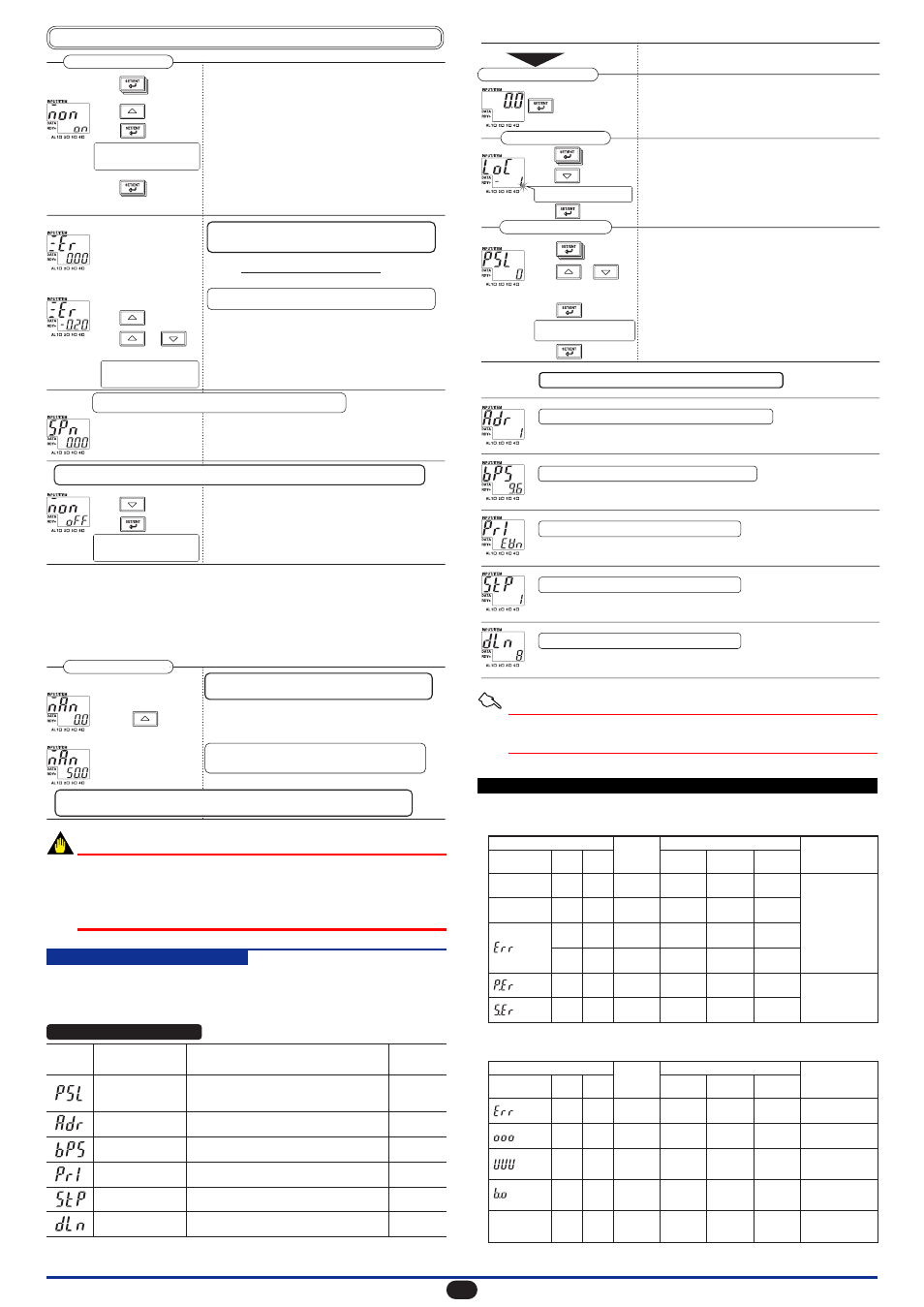
IM 77J04R31-01E 1st Edition : 2006.08.31-00
Press the SET/ENT key to display parameter "MON."
Press the UP key to display "ON" on the DATA display.
Press the SET/ENT key to accept the data.
Press the SET/ENT key twice to display parameter "ZER."
Display parameter "MON" and press the DOWN key to
display "OFF" on the DATA display.
Press the SET/ENT key to accept the data.
Press the UP key to display "-0.20" on the DATA display.
Then press the UP or DOWN key to make fine
adjustments.
Make adjustments to the maximum monitor output value
by displaying parameter "SPN."
The minimum output value
(1 V) is output forcibly.
The maximum output
value (5 V) is output
forcibly.
(Displays a correction value
corresponding to the error.)
Press to display
"-0.20."
Press or
to make fine adjustments.
Setup Parameter Screen 2
This establishes the setting in which
the monitor output adjustment
screen becomes visible.
This establishes the setting in which
the monitor output adjustment
screen becomes invisible.
This completes the process for
adjusting the minimum monitor
output value.
The MVRK enters the operable status as soon as the power is turned on, but requires 10 to 15 minutes
of warm-up to meet the performance requirements.
(Measured value [1.008 V]) - (Reference value [1 V])
Output span [4 V]
×
100 (%)
Error =
Follow the same procedure as above to adjust the maximum monitor
output value.
After adjusting the monitor output, set the MON parameter to "OFF" (making the adjustment
screen invisible).
When this parameter (ZER) is displayed, the MVRK forcibly outputs
the minimum monitor output value (0%), regardless of input.
The monitor output is corrected by -0.2% because the error is
+0.008 V (+0.2%).
Press to display
"MON."
Press to display
"ON."
Press .
Press to display
"ZER."
Press to display
"OFF."
Press .
12.1.5
Using the Forced Output Function
The use of the forced output function allows you to conduct operation tests for a device
connected to the monitor output terminals of the MVRK.
This subsection describes an example of forcing a value equivalent to 50% of the output
range (3 V) to output when the monitor output of the MVRK is “1 to 5 V DC.”
The procedure below begins with the condition in which parameter “MAN” is displayed
with the MON parameter set to “ON” in the Setup Parameter Screen 2.
Press the UP key to display "50.0" on the DATA display.
The minimum output value
(1 V) is output forcibly.
The value equivalent to
50% of the output range
(3 V) is output forcibly.
Setup Parameter Screen 2
When this parameter (MAN) is displayed, the MVRK forces
the monitor output value to be output, regardless of input.
3 V is output forcibly. The MVRK continues to output
while this parameter is displayed on the screen.
After completion of the forced output, return the MON parameter setting to "OFF" (making the
adjustment screen invisible).
Pressing causes
the output value to increase.
IMPORTANT
After performing monitor output adjustments or forced output, always set the MON
parameter to “OFF” (making the adjustment screen invisible). If the Setup Parameter
Screen 2 is switched while the MON parameter is set to “ON,” displaying parameter
“MAN,” “ZER” or “SPN” causes a value corresponding to the set value to be output
forcibly. Furthermore, if the power is turned off while parameter “MAN” is displayed, the
set values will be initialized.
12.2 Monitor Output (Communication)
Monitor output (communication) is added only when the monitor output code “P” is
specified at the time of order.
12.2.1
Setting Ranges and Factory-Set Values of Monitor Output (Communica-
tion)-Related Parameters
Setup Parameter Screen 2
0: PC link
3: MODBUS ASCII
1: PC link with SUM
4: MODBUS RTU
2: Ladder communication
1.2 (0: 1200 bps)
4.8 (2: 4800 bps)
2.4 (1: 2400 bps)
9.6 (3: 9600 bps)
NON (0: None)
ODD (2: Odd)
EVN (1: Even)
1 to 99
1 or 2 (bits)
7 or 8 (bits)
Parameter Name
Setting Range
Factory-Set
Value
Parameter
Symbol
0
(PC link)
1
9.6
(9600 bps)
EVN
(Even)
1
8
Communication
protocol (PSL)
Communication
address (ADR)
Baud rate
(BPS)
Parity
(PRI)
Stop bit
(STP)
Data length
(DLN)
12.2.2
Setting the Communication-Related Parameters
When you press the SET/ENT key for more than 3 sec.
with the Operation Parameter Screen displayed, the
Setup Parameter Screen 1 appears.
When the power is turned on, the PV screen of the
Operation Parameter Screen appears.
Press the SET/ENT key to display parameter "PSL" for
setting the communication protocol.
Press the UP or DOWN key to display the communication
protocol number on the DATA display.
Press this key for
more than 3 sec.
The decimal point blinks during
data change.
Press the SET/ENT key to display parameter "LOC."
Setup Parameter Screen 1
Setup Parameter Screen 2
Operation Parameter Screen
Power ON
This completes the process for
setting the communication protocol.
Parameter "PRI" for setting the parity
Parameter "STP" for setting the stop bit
Parameter "DLN" for setting the data length
Parameter "BPS" for setting the baud rate
Parameter "ADR" for setting the communication address
Follow the same procedure to set the following parameters:
Press to display
"LOC."
Press to display
"-1."
Press .
Press to display
"PSL."
Press or
to display the communication
protocol number to use.
Press .
Press .
Press the DOWN key to display "-1" on the DATA display.
Press the SET/ENT key to display the Setup Parameter
Screen 2.
Press the SET/ENT key to accept this data.
Press the SET/ENT key to display the next parameter.
See Also
For more information on the communication functions, refer to the M Series Digital
Limit Alarms Communication Functions User’s Manual (IM 77J04J11-01E) sold
separately.
13. TROUBLESHOOTING
Error Indication
Description
of Error
PV
Status
Alarm
Output
Monitor
Output
Remedy
Possible Errors Occurring at Power ON
The following describes possible errors occurring at power ON.
Possible Errors Occurring during Operations
The following describes errors that may occur during operations.
PV Display
Alarm
Indicator
Lamps
READY
Lamp
Error Indication
Description
of Error
PV
Status
Alarm
Output
Monitor
Output
Remedy
PV Display
Alarm
Indicator
Lamps
READY
Lamp
Undefined
Undefined
OFF
OFF
OFF
Blinking
Blinking
Normal
Normal
Normal
Normal
Normal
Normal
Normal
AL2
blinking
AL1
lights
Undefined
Undefined Undefined
Undefined
OFF
Normal
Normal
Normal
Normal
Normal
Normal
None (0%)
OFF
OFF
OFF
None
(0%)
None
(0%)
None
(0%)
0% or less
0% or less
0% or less
0% or less
CPU
failure
Power
failure
RAM
error
ROM
error
Parameter
error
EEP sum
error
EEPROM
error
OFF
blinks
blinks
Failure.
Submit request for us to
repair.
Failure.
Submit request
for us to repair.
Check all
parameters.
Normal
Burnout
Normal
Normal
Normal
Normal
Decimal point
blinks
Press any key, or if
normal communication is
made, a communication
error will be cleared.
Normal
Communication
error
Normal
Normal
Normal
Normal
Normal
Normal
Check input.
Check input.
Check input.
Input
exceeding
high limit
110% of the
measured
range
106% or more
of the output
range
-6% or less
of the output
range
106% or more
or -6% or less
of the output range
-10% of the
measured
range
110% or -10%
of the measured
range
Input falling
below low
limit
7