Bc d d c – Yokogawa JUXTA M Series Digital Limit Alarms MVRK User Manual
Page 2
IM 77J04R31-01E 1st Edition : 2006.08.31-00
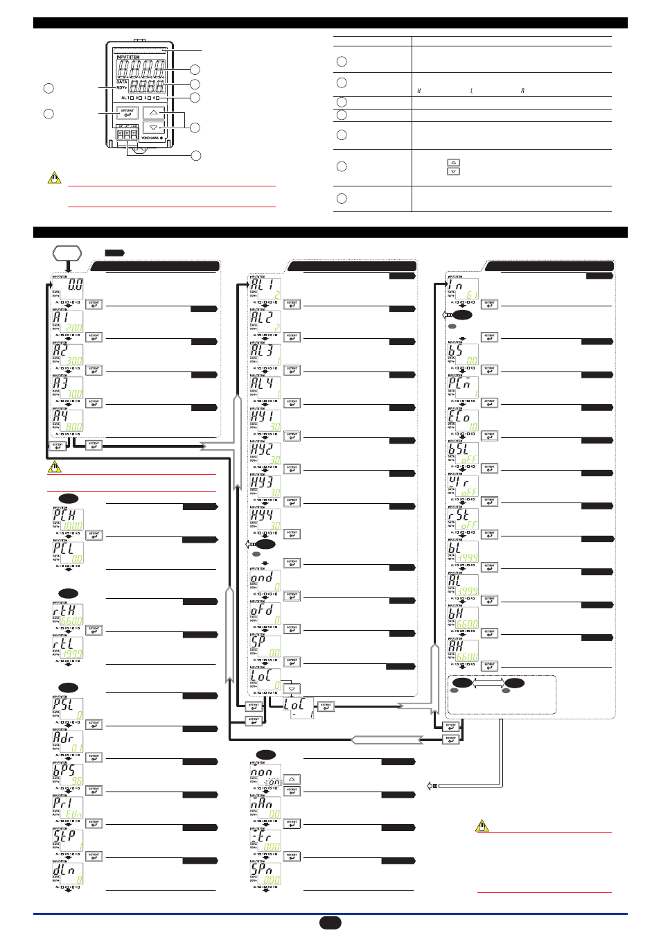
4. PART NAMES OF FRONT PANEL AND THEIR FUNCTIONS
PV (measured value) display
Place for adhering
the tag number label
DATA display
Alarm indicator lamp
2 points of alarms: 2 lamps
4 points of alarms: 4 lamps
Monitor output terminal
(option)
UP/DOWN key
SET/ENT key
READY lamp
Part Name
PV (measured value)
display
DATA display
Alarm indicator lamp
READY lamp
SET/ENT key
UP/DOWN key
Monitor output terminal
(Two-piece connector)
Function
Displays a measured value during operation.
Displays a parameter symbol when a parameter is set.
Displays an error code in the event of an error.
Displays the setpoint of a variety of parameters.
Displays an alarm type in the event of an alarm. (Not displayed during normal operation.)
: High-limit alarm : Low-limit alarm : Other alarms
1
2
3
5
4
6
7
1
2
3
6
7
5
4
The front panel of the product is constructed to prevent opening.
Forcing it open will result in breakage.
NOTE
In the event of an alarm, AL1 to AL4 (alarm 1 to alarm 4) light up.
Lights up when the power is turned on.
Used to switch parameter indication or accept a setpoint.
Pressing this key for more than 3 seconds allows you to select the Operation
Parameter Screen and Setup Parameter Screen alternately.
Used to change the setpoint of a parameter.
Pressing the key increases a numerical value.
Pressing the key decreases a numerical value.
Holding down a key accelerates the speed of change.
Outputs 1 to 5 V DC, 4 to 20 mA DC or RS-485 communication signal.
(To be added only when the monitor output has been specified at the time of
order.)
5. SWITCHING PARAMETERS
Operation Parameter Screen
Setup Parameter Screen 1
Setup Parameter Screen 2
To the Operation Parameter Screen
A
A
A
is displayed when the PV display color mode (PCM) has been set to 6, 7, 8 or 9.
Press this key for more than 3 sec.
Press this key
for more than 3 sec.
Press this key
for more than 3 sec.
A
D
C
B
B
B
C
D
D
C
or
Press the DOWN key to display "-1"
on the DATA display and then press
the SET/ENT key.
Power
ON
Displays a measured value.
In this manual, this screen is called the "PV
(measured value) screen."
Alarm-1 setpoint (A1)
Sets the alarm-1 setpoint.
Alarm-2 setpoint (A2)
Sets the alarm-2 setpoint.
Alarm-3 setpoint (A3)
(Displayed only for 4 points of alarms)
Sets the alarm-3 setpoint.
Alarm-4 setpoint (A4)
(Displayed only for 4 points of alarms)
Sets the alarm-4 setpoint.
Alarm-1 action (AL1)
Sets the direction of alarm-1 action.
(See the Alarm Action Type Codes table in Section 8.1.)
Range code No. (IN)
Sets the range code number (input type).
Measured input bias (BS)
This parameter is set to correct a measured
input value.
PV display color mode (PCM)
Sets the Active color PV display.
Economical mode time (ECO)
This parameter is set to extinguish the display
(not including the READY and alarm lamps) if no
keystroke is made for a specified time.
Input adjustment reset (RST)
Used to reset an input adjustment value.
Input adjustment point LOW (BL)
Sets the reference value corresponding to
0% of the input when an input adjustment is
made.
Input adjustment LOW (AL)
Adjusts the 0% value of an input.
Input adjustment point HIGH (BH)
Sets the reference value corresponding to
100% of the input when an input adjustment
is made.
Input adjustment HIGH (AH)
Adjusts the 100% value of an input.
Alarm-2 action (AL2)
Sets the direction of alarm-2 action.
(See the Alarm Action Type Codes table in Section 8.1.)
Alarm-3 action (AL3)
(Displayed only for 4 points of alarms)
Sets the direction of alarm-3 action.
(See the Alarm Action Type Codes table in Section 8.1.)
Alarm-4 action (AL4)
(Displayed only for 4 points of alarms)
Sets the direction of alarm-4 action.
(See the Alarm Action Type Codes table in Section 8.1.)
Alarm-1 hysteresis (HY1)
Sets the hysteresis of alarm 1.
Alarm-2 hysteresis (HY2)
Sets the hysteresis of alarm 2.
Alarm-3 hysteresis (HY3)
(Displayed only for 4 points of alarms)
Sets the hysteresis of alarm 3.
Alarm-4 hysteresis (HY4)
(Displayed only for 4 points of alarms)
Sets the hysteresis of alarm 4.
Alarm ON delay (OND)
Sets the condition monitoring time from the
establishment of alarm conditions to its
output.
Alarm OFF delay (OFD)
Sets the condition monitoring time from the
establishment of return-to normal conditions
to its output.
Setpoint (SP)
When using a deviation alarm, this
parameter is set to the value treated as the
reference for deviations.
Key lock (LOC)
This parameter is set when change of parameter
settings (all parameters or parameters other than the
operation parameters) is locked to prevent wrong
operations.
Visibility of monitor output adjustment screen (MON)
Sets the visibility of the screen for adjusting monitor
output. Pressing the SET/ENT key with "ON"
displayed on the DATA display causes the
adjustment screen to appear.
Forced output of a monitor output value (MAN)
Used to force a value equivalent to -25% to +125%
of an analog output value to output, regardless of
input.
Monitor output zero adjustment (ZER
)
Adjusts the zero point of the monitor output.
Monitor output span adjustment (SPN
)
Adjusts the span of the monitor output.
Maximum monitor output value (RTH)
This parameter is set to treat any value as
the maximum output value with respect to
the input range.
High limit for PV display color change (PCH)
Sets the high limit for PV limit mode or SP
deviation mode of Active color PV display.
Low limit for PV display color change (PCL)
Sets the low limit for PV limit mode or SP
deviation mode of Active color PV display.
Minimum monitor output value (RTL)
This parameter is set to treat any value as
the minimum output value with respect to the
input range.
Communication protocol (PSL)
Sets the communication protocol.
Communication address (ADR)
Sets the communication address.
Baud rate (BPS)
Sets the baud rate.
Parity (PRI)
Sets the parity.
Stop bit (STP)
Sets the stop bit.
Data length (DLN)
Sets the data length.
If no keystroke is made for more than 2 minutes,
the PV screen automatically appears, regardless
of the parameter displayed. In this case, if a data
change is in progress (the decimal point is
blinking), the data being changed becomes invalid
and the PV screen appears with the previous data
displayed as is.
However, this action does not take place if the
parameter "MAN", "ZER" or "SPN" is being
displayed.
NOTE
If the alarm action (AL1 to AL4) is set to "OFF," the relevant alarm
setpoint (A1 to A4) is not displayed.
NOTE
Chapter 7
Chapter 11
Chapter 11
Chapter 10
Burnout action (BSL)
Sets the burnout action.
Wiring resistance correction (WIR)
Used when correcting wiring resistance.
Chapter 7
Chapter 7
Chapter 9
Chapter 9
Chapter 9
Chapter 9
Chapter 9
Section 12.1
Section 12.1
Section 12.1
Section 12.1
Section 12.1
Section 12.1
Section 12.2
Section 12.2
Section 12.2
Section 12.2
Section 12.2
Section 12.2
Chapter 8
Chapter 8
Chapter 8
Chapter 8
Chapter 8
Chapter 8
Chapter 8
Chapter 8
Chapter 8
Chapter 8
Chapter 8
Chapter 8
Chapter 8
Chapter 8
Chapter 11
T
o
the Setup Parameter Screen 1
T
o
the Operation Parameter Screen
Chapter 8
To
the Setup Parameter Screen 2
is displayed when the monitor output (analog) has been specified.
is displayed when the
monitor output (RS-485
communication) has been
specified.
The
symbol indicates a reference chapter/section in this manual.
A
Chapter 10
Chapter 10
is displayed
when the monitor
output (analog) has
been specified.
2