Description of front panel, Power supply and isolaion, 1 operation indicating lamp – Yokogawa JUXTA MU5D User Manual
Page 3: 2 connector for communication, 3 selection switch and adjustment switch
3
IM 77J04U05-02E
3rd Edition Oct. 15, 2007-00
Power Supply and Isolaion
Power supply rated voltage:
15-40 V DC or 100-240 V AC/DC 50/60 Hz
Power supply input voltage:
15-40 V DC (
±
20%) or 100-240 V AC/DC (
−
15,
+
20%) 50/60
Hz
Power consumption:
24 V DC 2.3 W, 110 V DC 2.2 W
100 V AC 4.6 VA, 200 V AC 6.4 VA
Insulation resistance:
100 M
Ω
at 500 V DC between input, output, power supply, and
grounding terminals mutually.
Withstand voltage:
2000 V AC for 1 minute between input, output, power supply and
grounding terminals mutually.
1000 V AC for 1 minute between output-1 and output-2 terminals.
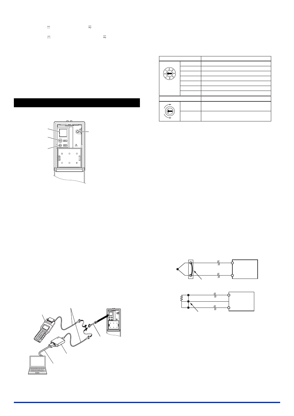
4. DESCRIPTION OF FRONT PANEL
The figure below shows the converter of which the front panel cover is
open.
Connector for
communication
Selection
switch
Adjustment
switch
Operation indicating lamp:
Turns on at power on.
4.1 Operation Indicating Lamp
The operation indicating lamp shows the operation status, abnormali-
ties in a setting, and adjustment operation status by the adjustment
switch on the front panel.
(1) When the lamp is lit:
Power is turned on and the converter is in the normal status pro-
vided that the selection switch is set to the position “0.”
(2) When the lamp is blinking rapidly:
The lamp repeats the rapid blinking until the internal processing is
completed during output adjustment and wiring resistance correc-
tion by the adjustment switch.
(3) When the lamp is blinking slowly:
The lamp repeats the slow blinking until the converter regains its
normal status when the following abnormalities occur.
• Abnormalities in a parameter setting
• The selection switch is set to the positions other than “0.”
•
Input is outside of the range of
−
10 to 110%.
•
OFF of RJC and error of RJC.
4.2 Connector for Communication
Use the connector for communication when setting the parameters us-
ing a PC (VJ77 Parameter Setting Tool) or the Handy Terminal.
PC which is installed
with the VJ77.
*: Use the VJ77 of version R1.04 or later.
JHT200
Handy Terminal
JUXTA communication cable with
5-pin connector (F9182EE)
[Provided with VJ77 and JHT200]
Modular jack conversion
adapter (E9786WH)
[Provided with VJ77]
Dedicated adapter (E9789HA)
[Provided with VJ77]
Dedicated cable (E9786WK)
[Provided with VJ77]
4.3 Selection Switch and Adjustment Switch
The following adjustments can be performed using the switches on the
front panel (selection switch and adjustment switch) without the dedi-
cated setting tool (refer to“4.2 Connector for Communication”).
The adjusted value is saved about 1 second after operating the adjust-
ment switch. Also when the rotation direction of the adjustment switch
is changed, the adjusted value becomes effective about 1 second after
the change.
Position of selection switch
0
1
2
3
4
5
7
Rotation direction of adjustment switch
Clockwise
Counterclockwise
Item to be adjusted
No function
Output-1 zero adjustment
Output-1 span adjustment
Output-2 zero adjustment
Output-2 span adjustment
Wiring resistance correction
ON/OFF of RJC
Adjustment operation
Increase of output adjusted value, execution of
wiring resistance correction and ON of RJC
Decrease of output adjusted value, reset of wiring
resistance corrected value and OFF of RJC
[Adjusted volume by the adjustment switch]
One click changes about 0.005% of output range.
For thermocouple input, turn off the RJC.
4.3.1 Adjusting Output Using the Switches on the Front
Panel
(1) Output-1 zero adjustment
Apply the 0% input signal. Turn the selection switch to “1.” Then
turn the adjustment switch clockwise to increase the output, or
turn it counterclockwise to decrease the output.
(2) Output-1 span adjustment
Apply the 100% input signal. Turn the selection switch to “2.” Then
turn the adjustment switch clockwise to increase the output, or
turn it counterclockwise to decrease the output.
Output-2 can be adjusted by the same operation as the above.
(3) Output-2 zero adjustment
Apply the 0% input signl. Turn the selection switch to “3.” Use the
adjustment switch for adjustment.
(4) Output-2 span adjustment
Apply the 100% input signal. Turn the selection switch to “4.” Use
the adjustment switch for adjustment.
4.3.2 Correcting the Wiring Resistance Using the Switches on the Front Panel
When an error occurs due to the influence of the input wiring resis-
tance, perform the wiring as the figure below, apply a stable input, and
execute the following operations. Then the wiring resistance can be
corrected automatically.
MU5D
Short-circuit at the cable end.
MU5D
Short-circuit at the cable end.
Be sure to turn the adjustment switch counterclockwise to reset the
corrected value before executing the wiring resistance correction.
(1) Executing the wiring resistance correction
Turn the selection switch to “5”, and turn the adjustment switch
clockwise. Then the wiring resistance is adjusted after 1 second
automatically.
(2) Resetting the wiring resistance corrected value
Turn the selection switch to “5”, and turn the adjustment switch
counterclockwise. Then the adjusted value is reset after 1 sec-
ond.