Setting parameters, 2 connecting the setting tools, 1 settings related to input – Yokogawa JUXTA VJAK User Manual
Page 3: 2 settings related to alarm output
3
IM 77J01A21-01E
1st Edition : 2006.08.15-00
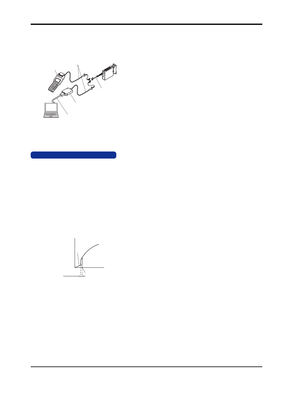
8.2 Connecting the Setting Tools
Connect the modular jack conversion adapter (E9786WH) to
the JUXTA communication cable with 5-pin connector
(F9182EE) and then connect this adapter to the communica-
tion connector of JUXTA.
JHT200
Handy Terminal
JUXTA communication cable with
5-pin connector (F9182EE)
[Comes with VJ77 and JHT200]
Modular jack conversion
adapter (E9786WH)
[Comes with VJ77]
Dedicated adapter (E9789HA)
[Comes with VJ77]
Dedicated cable (E9786WK)
[Comes with VJ77]
PC with the
VJ77 installed
Fig. 8.2 Connecting the Setting Tools
Note: The modular jack conversion adapter does not
come with the JHT200 Handy Terminal.
It is sold separately.
9. SETTING PARAMETERS
Set the parameters using a PC (VJ77 PC-based Parameters
Setting Tool) or the Handy Terminal (JHT200). Refer to the list
of parameters in this manual and the user’s manual for VJ77
PC-based Parameters Setting Tool (IM 77J01J77-01E) or
JHT200 Handy Terminal (IM JF81-02E).
9.1 Settings Related to Input
9.1.1 Square Root Extraction Function
Select SQR in D11: LINEARIZE to set “with square root ex-
traction function.”
9.1.2 Low-cut Function
Set the low-cut point in D12: LOW CUT numerically when
“with square root extraction function” is set.
●
Setting range: 0 to 100% of input range
●
Setting resolution: 0.1%
Input signal (X)
Output signal
(Y)
0
Low-cut point
Hysteresis
(0.2% fixed)
Y=X
9.2 Settings Related to Alarm Output
9.2.1 Alarm Setpoint
Set the alarm setpoints of alarm 1 and alarm 2 in E03: SET
POINT1 and E04: SET POINT2 numerically.
●
Setting range: 0 to 100% of input range
●
Setting resolution: 0.1%
9.2.2 Direction of Alarm Action
Select the direction of alarm-1 action and that of alarm-2 ac-
tion from among HIGH ALM (high-limit alarm) and LOW ALM
(low-limit alarm) in E05: ALM1 ACTION and E06: ALM2 AC-
TION .
●
To activate alarm status when input signal
Ն
alarm
setpoint, select HIGH ALM.
●
To activate alarm status when input signal
Յ
alarm
setpoint, select LOW ALM.
9.2.3 Hysteresis
Set the alarm-1 and alarm-2 hysteresis in E09: HYSTER-
ESIS1 and E10: HYSTERESIS2. Hysteresis is a value
added to the alarm setpoint in order for an alarm status to be
released (to normal) after the alarm status has been acti-
vated. The alarm status will be released in the following con-
ditions, depending on the direction of alarm action.
*
When HIGH ALM (high-limit alarm) is set: Alarm is re-
leased when input signal < (alarm setpoint - hysteresis).
*
When LOW ALM (low-limit alarm) is set: Alarm is re-
leased when input signal > (alarm setpoint + hysteresis).
●
Setting range: 0 to 100% of input range
●
Setting resolution: 0.1%
9.2.4 Alarm ON Delay and Alarm OFF Delay
Set the alarm-1 and alarm-2 ON delays in E11: ON DELAY1
and E12: ON DELAY2 and then alarm-1 and alarm-2 OFF
delays in E13: OFF DELAY1 and E14: OFF DELAY2.
An alarm ON delay is the condition monitoring time from the
establishment of alarm conditions to its output; an alarm OFF
delay is the condition monitoring time from the establishment
of return-to-normal conditions to its output.
●
Setting range: 0 to 999 seconds
●
Setting resolution: 1 second (However, about 0.2 sec-
ond is to be added to the set time to prevent wrong op-
eration.)
For example, when an alarm ON delay is set to 1 second,
alarm output is generated if alarm status continues for 1 sec-
ond or more after the input value exceeds the alarm
setpoint. Further, when an alarm OFF delay is set to 2 sec-
onds, alarm output is released if normal condition continues
for 2 seconds or more after the input value has returned to
normal from the alarm status.
9.2.5 Direction of Relay Action
Select the direction of relay energizing in alarm-1 normal
condition and alarm-2 normal condition from among NRM
DE-ENERGIZED (de-energized under normal condition) and
NRM ENERGIZED (energized under normal condition) in
E15: RL1 ACTION and E16: RL2 ACTION.