Installation locations, External wiring, 2 din rail mounting – Yokogawa JUXTA VJAK User Manual
Page 2: 3 using a duct, 1 front panel, Warning, Important
2
All Rights Reserved. Copyright © 1999, Yokogawa M&C Corporation
IM 77J01A21-01E
1st Edition : 2006.08.15-00
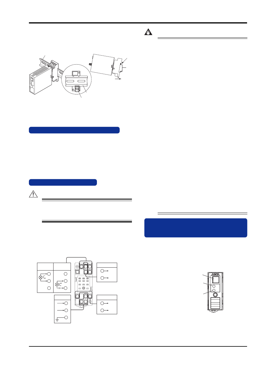
5.2 DIN Rail Mounting
Locate the VJAK so that the DIN rail fits into the upper part
of the DIN-rail groove at the rear of the socket, and fasten
the socket using the slide lock at the lower part of the
socket.
DIN
rail
Fit into
here
Push
DIN rail
(Rear of the socket)
Slide lock
DIN rail
Fig. 5.2
5.3 Using a Duct
Wiring duct should be installed at least 30 mm away from
the top and bottom faces of the main unit.
6. INSTALLATION LOCATIONS
•
Avoid the following environments for installation locations:
Areas with vibrations, corrosive gases, dust, water, oil,
solvents, direct sunlight, radiation, a strong electric field,
and/or a strong magnetic field.
•
If there is any risk of a surge being induced into the
power line and/or signal lines due to lightning or other
factors, a dedicated lightning arrester should be used as
protection for both the product and a field-installed de-
vice.
7. EXTERNAL WIRING
WARNING
To avoid the risk of an electric shock, turn off the
power supply and use a tester or similar device to
ensure that no power is supplied to a cable to be
connected, before carring out wiring work.
Wiring should be connected to the terminals on the socket of the
VJAK. The terminals for external connections are of M3 screws.
Use crimp-on lugs for connections to the terminals.
•
It is recommended that signal wires have a nominal
cross-sectional area of 0.5 mm
2
or thicker, while the
power cable has a nominal cross-sectional area of 1.25
mm
2
or thicker.
10
11
3
2
1
4
5
6
7
8
9
3
1
3
1
4
4
11
10
8
5
2
9
7
GND
L
+
N
COM
ALM2 (NO)
COM
COM
ALM1 (NO)
COM
PS
+
Input signal
+
–
–
+
–
–
–
When using
internal
power supply
When using
external
power supply
Power supply
When connecting the transmitter to the VJAK directly without using the transmitter
power supply, connect [+] of the transmitter output to the terminal no. 3 and connect [–]
to the terminal no. 4.
Alarm-1 output
Alarm-2 output
IMPORTANT
●
Use of the product ignoring the specifications
may cause overheating or damage. Before
turning on the power, ensure the following:
(a) Power supply voltage and input signal
value applied to the product should meet
the required specifications.
(b) The external wiring to the terminals and
wiring to ground are as specifications.
●
Do not operate the product in the presence of
flammable or explosive gases or vapors. To do
so is highly dangerous.
●
The product is sensitive to static electricity;
exercise care in operating it. Before you
operate the product, touch a nearby metal part
to discharge static electricity.
●
If an inductance (L) load such as auxiliary
relays or solenoid valves is used, always insert
a spark killer for diminishing sparks, such as a
CR filter or a diode in parallel with the
inductance load. Otherwise a malfunction or
relay failure may occur. Refer to the following
guidelines for a capacitor and resistor:
Capacitor : 0.5 to 1
F with respect to a contact
current of 1 A
Resistor: 0.5 to 1
Ω
with respect to a contact
voltage of 1 V
●
The power line and input/output signal lines
should be installed away from noise-
generating sources. Otherwise accuracy
cannot be guaranteed.
●
The grounding resistance must be 100
Ω
(JIS
Class D grounding). The length and thickness
of the grounding cable should be as short and
thick as possible. Directly connect the lead
from the ground terminal (terminal no. 8) of the
product to the ground. Do not carry out daisy-
chained inter-ground terminal wiring.
8. DESCRIPTION OF FRONT PANEL
AND CONNECTION OF SETTING
TOOLS
8.1 Front Panel
The communications connector on the front panel is used for
setting up parameters using a PC (VJ77 PC-based Param-
eters Setting Tool) or the Handy Terminal (JHT200). The
alarm indicator lamps for alarm 1 and alarm 2 light up if an
alarm occurs.
ALM1
ALM2
Alarm indicator lamp
(for alarm 1)
Communication connector
Alarm indicator lamp
(for alarm 2)
Fig. 8.1 Front Panel