Description of alarm actions, Timing chart of pulse integration operation, 2 settings related to communication function – Yokogawa JUXTA VJQ8 User Manual
Page 4: 3 settings related to alarm output, 1 communication protocol, 2 communication address, 3 baud rate, 4 parity, 5 data length, 6 stop bit
4
IM 77J01Q08-01E 4th Edition
Mar. 02, 2012-00
5.2 Settings Related to Communication
Function
Set the following parameters when output-2 is specified
for communication function. For more information on the
communication function, see the Instruction Manual for VJ Series
Communication Function (IM 77J1J11-01E).
5.2.1 Communication Protocol
Set the communication protocol by selecting from among
PCLINK, PC-LINK WITH SUM, MODBUS ASCII, MODBUS
RTU, and LADDER in
[F01: PROTOCOL].
5.2.2 Communication Address
Set the address number of the isolator numerically in a range
of 1 to 99 in
[F02: ADDRESS].
5.2.3 Baud Rate
Set the baud rate by selecting from among 1200, 2400, 4800,
and 9600 bps in
[F03: BAUD RATE].
5.2.4 Parity
Select and set NONE, EVEN, or ODD in
[F04: PARITY].
5.2.5 Data Length
Select and set 7 bits or 8 bits in
[F05: DATA LEN].
5.2.6 Stop Bit
Select and set 1 bit or 2 bits in
[F06: STOP BIT].
5.2.7 Input Decimal Point Position
Number of digits of decimal places can be set.
Select and set among 0 to 5 digits in
[F07: INPUT DEC PT].
5.3 Settings Related to Alarm Output
Set the following parameters when output-2 is specified for alarm
output.
5.3.1 Alarm Setpoints
Set the alarm setpoints of alarm-1 and alarm-2 in
[E03: SET
POINT1] and [E04: SET POINT2] numerically.
Setting range: A range of 0 to 100% of input range
Setting resolution: 0.1%
5.3.2 Direction of Alarm Action
Select the direction of alarm-1 action and that of alarm-2
action from among HIGH ALM (high-limit alarm) and LOW
ALM (low-limit alarm) and set each in
[E05: ALM1 ACTION]
(direction of alarm-1 action) or
[E06: ALM2 ACTION]
(direction of alarm-2 action).
To activate alarm status when input signal ≥ alarm setpoint,
select HIGH ALM.
To activate alarm status when input signal ≤ alarm setpoint,
select LOW ALM.
5.3.3 Hysteresis
Set alarm-1 and alarm-2 hysteresis, in
[E09: HYSTERESIS1]
and
[E10: HYSTERESIS2]. Hysteresis is a value added to the
alarm setpoint in order for an alarm status to be released (to
normal) after the alarm status has been activated. The alarm
status will be released in the following conditions, depending
on the direction of alarm action.
* When HIGH ALM (high-limit alarm) is set: Alarm is released
when input signal < (alarm setpoint - hysteresis).
* When LOW ALM (low-limit alarm) is set: Alarm is released
when input signal > (alarm setpoint + hysteresis).
Setting range: A range of 0 to 100% of input range
Setting resolution: 0.1%
5.3.4 Alarm ON Delay and Alarm OFF Delay
Set alarm-1 and alarm-2 ON delays in
[E11: ON DELAY1] and
[E12: ON DELAY2] and then alarm-1 and alarm-2 OFF delays
in
[E13: OFF DELAY1] and [E14: OFF DELAY2]. An alarm
ON delay is a delay time from the establishment of alarm
condition to alarm output; an alarm OFF delay is a delay time
from the establishment of return-to-normal condition to output.
Setting range: 0 to 999 seconds
Setting resolution: 1 second (Note that about 0.2 second will
be added to set time to prevent erroneous operation.)
For example, when an alarm ON delay is set to 1 second,
alarm output is generated if alarm status continues for
more than 1 second after the input value exceeds the
alarm setpoint. Further, when an alarm OFF delay is set
to 2 seconds, alarm output is released if normal condition
continues for more than 2 seconds after the input value has
returned to normal from the alarm status.
5.3.5 Direction of Relay Action
Set the direction of relay energizing in alarm-1 normal
condition and alarm-2 normal condition by selecting from
among NRM DEENERGIZED (de-energized under normal
condition) and NRM ENERGIZED (energized under normal
condition) in
[E15: RL1 ACTION] and [E16: RL2 ACTION]
and set them.
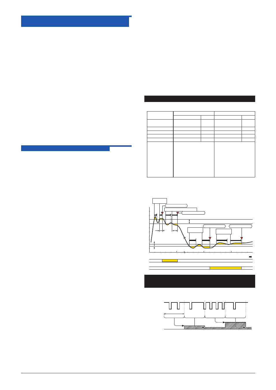
6. DESCRIPTION OF ALARM ACTIONS
This chapter describes examples of alarm actions under the
following conditions.
Item
Alarm-1
Alarm-2
Parameter
Setpoint Parameter
Setpoint
Direction of alarm
action
E05: ALM1 ACTION High-limit
alarm
E06: ALM2 ACTION Low-limit
alarm
Alarm setting
E03: SET POINT1
80%
E04 : SET POINT2
15%
Hysteresis
E09: HYSTERESIS1 10%
E10 : HYSTERESIS2 5%
Alarm ON delay
E11: ON DELAY1
1 sec.
E12 : ON DELAY2
3 sec.
Alarm OFF delay
E13: OFF DELAY1
2 sec.
E14 : OFF DELAY2 4 sec.
Description of alarm
actions
The alarm sounds if the
condition where the input value
is 80% or more of high-limit
alarm continues for more than 1
second. After the alarm sounds,
when the condition where
input value is less than 70%of
the high-limit alarm continues
for more than 2 seconds, the
status returns to normal
The alarm sounds if the
condition where the input value
is 15% or less of low-limit
alarm continues for more than
3 seconds. After the alarm
sounds, when the condition
where input value is more than
20% of the low-limit alarm
continues for more than 4
seconds, the status returns to
normal.
Alarm-1 action
Alarm-2 action
Normal
Normal
Normal
Normal
Alarm
Alarm
[%]
0
20
15
40
60
80
100
1 sec.
2 sec.
3 sec.
4 sec.
Alarm-2 hysteresis (5%)
Alarm-1 hysteresis (10%)
Alarm-1 setpoint (80%)
Alarm-2 setpoint (15%)
Elapsed time 1 sec.
[1]
[2]
[3]
[4]
[1]: Alarm status does not continue for more than 1 second after
the alarm conditions are established at alarm-1.
[2]: Normal status does not continue for more than 2 seconds after
the normal conditions are established at alarm-1.
[3]: Alarm status does not continue for more than 3 seconds after
the alarm conditions are established at alarm-2.
[4]: Normal status does not continue for more than 4 seconds after
the normal conditions are established at alarm-2.
Alarm-1
ON delay
Alarm-2
ON delay
Alarm-2
OFF delay
Alarm-1
OFF delay
Alarm conditions
established
Alarm conditions
established
Normal conditions
established
Normal conditions established
High-limit alarm ON
Low-limit alarm ON
High-limit alarm OFF
Low-limit alarm OFF
7. TIMING CHART OF PULSE
INTEGRATION OPERATION
This timing chart shows an example of the integration operation
where input frequency is 0 to 10 Hz and sampling time is 2 sec.
10%
2 sec
0%
ON
ON
ON
ON ON ON ON
ON
Sampling
interval
Analog
output
Input pulse
5%
5%
20%