Description of front panel, Setting parameters, 1 front panel – Yokogawa JUXTA VJQ8 User Manual
Page 3: 2 connector for communication, 1 settings related to inputs and outputs
3
IM 77J01Q08-01E 4th Edition
Mar. 02, 2012-00
4. DESCRIPTION OF FRONT PANEL
4.1 Front Panel
The communications connector in the front panel is used for
setting up parameters through a PC (VJ77 PC-based Parameters
Setting Tool) or the Handy Terminal.
Communications connector
Alarm-1 LED
Alarm-2 LED
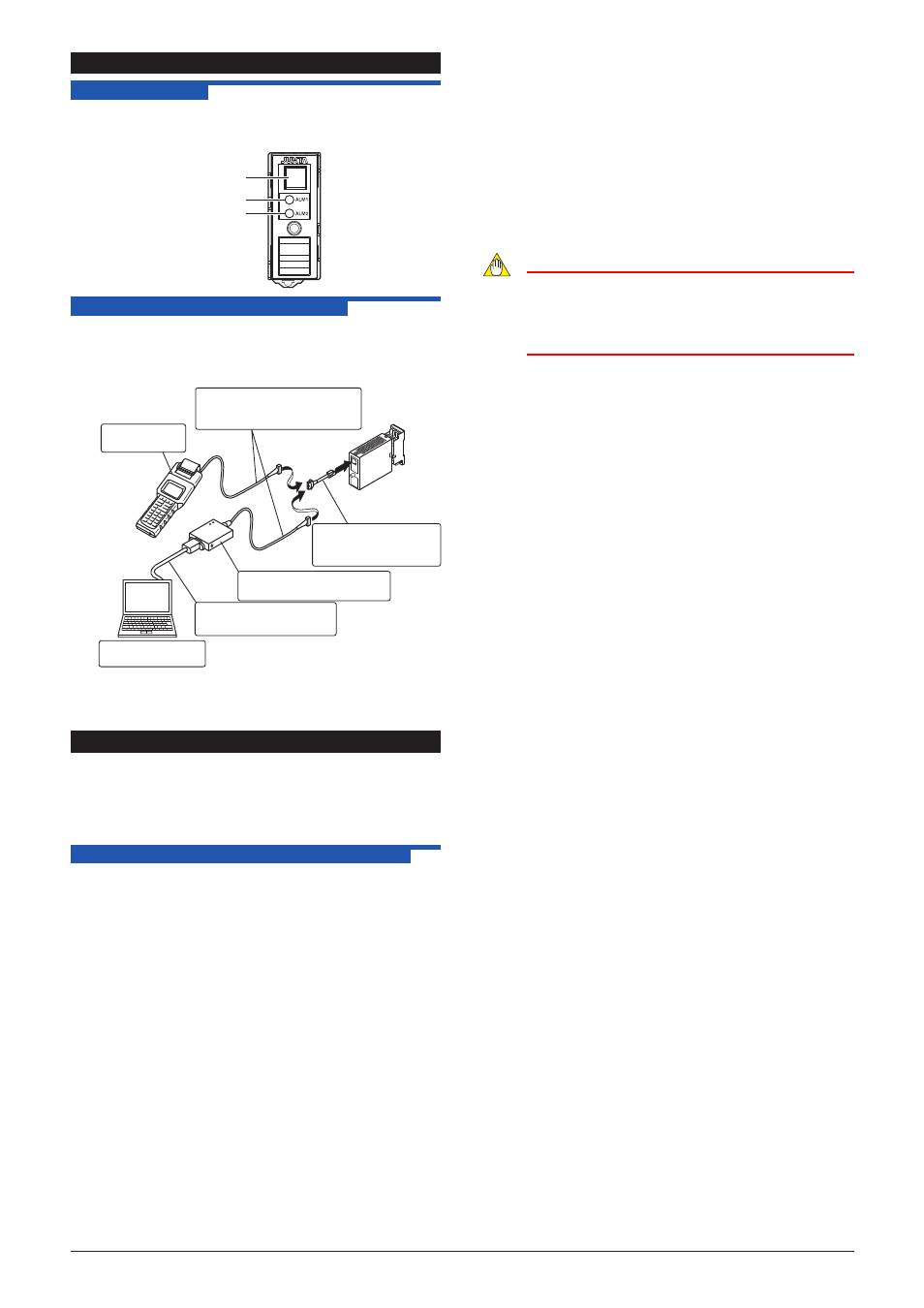
4.2 Connector for Communication
Use the connector for communication when setting the
parameters using a PC (VJ77 Parameters Setting Tool) or the
Handy Terminal
How to connect with the setting tool
Modular jack conversion
adapter (E9786WH)
[Provided with VJ77]
JHT200
Handy Terminal
JUXTA communication cable
with 5-pin connector (F9182EE)
[Provided with VJ77 and JHT200]
Dedicated adapter (E9789HA)
[Provided with VJ77]
PC which is installed
with the VJ77
Dedicated cable (E9786WK)
[Provided with VJ77]
• Use the VJ77 of version R1.04 or later.
• The modular jack conversion adapter does not come with the
JHT200 Handy Terminal. It is sold separately.
5. SETTING PARAMETERS
Set the parameters using a PC (VJ77 Parameter Setting Tool) or
the Handy Terminal. Refer to
“8. LIST OF PARAMETERS” in this
manual and the User’s Manual for VJ77 PC-based Parameters
Setting Tool (IM 77J01J77-01E) or the User’s Manual for JHT200
Handy Terminal (IM JF81-02E). Parameters are indicated inside
the
[ ].
5.1 Settings Related to Inputs and Outputs
5.1.1 Input Range Unit
When referring and setting the input range, select and set “Hz”
or “kHz” in
[D10: UNIT]. Select “kHz” when input range is over
32000Hz.
5.1.2 Conversion Mode
Select and set the action of the instrument from “F/V
CONVERTER” (F/V conversion) or “INTEGRATOR” (pulse
integrator) in
[D19: SELECT MODE].
F/V converter: Set when converting 0 to 100% of frequency
input to 0 to 100% of analog output, and
outputting it.
INTEGRATOR: Set when converting 0 to 100% of frequency
in put to 0 to 100% of analog output after
computing the average frequency from the
pulse number integrated per sample time, and
outputting it.
5.1.3 Sample Mode
Select and set “AUTO” or “MANUAL” in
[D20: SAMPLE
MODE], when the conversion mode is set to “INTEGRATOR.”
AUTO:
Outputs the sample time forcibly on the provided
MANUAL: Sets the sample time within setting range.
5.1.4 Sample Time
When the sample mode is set to “MANUAL”, set the sample
time in numerical value in
[D21: SAMPLE TIME], Sample
time setting range: 0.1 to 100 seconds, by 0.1 second When
the sample mode is set to “AUTO”, the sample time is forcibly
decided on the following conditions.
0.1 second when F
100
(100% input frequency) is 1kHz or more
(1/F
100
) 100 seconds when F
100
is over 1Hz and below 1kHz
100 seconds when F
100
is 1Hz or less.
5.1.5 Input Range
Set the 0% value of input range in
[D22: INPUT1L_RNG],
and 100% of input range in
[D23: INPUT1H_RNG] within the
numerically specified range.
Note
In case the input range is changed after factory-ship,
the instrument may not work within the rated accuracy
range depending on the changed input range. Perform
the adjustment following the maintenance of this
instruction manual after changing the input range.
5.1.6 Input Filter
When the chattering noise is generated in input, the input filter
is used to restrain the influence. Select and set “ON” in
[D50:
INPUT FILTER], then the input filter for time constant of about
10ms will be connected.
5.1.7 Direction of Output Action
Analog output signals can be reversed. To reverse the
signal from output-1, set
[D38: OUT1 DR] to REVERSE. For
output-2, set
[D39 OUT2 DR] to REVERSE. To return the
output-1 signal to normal, set D38: OUT1 DR to DIRECT. For
output-2, set D39: OUT2 DR to DIRECT.