Calibration – Yokogawa PH18 Differential pH Sensor User Manual
Page 14
14
IM 12B6J4-E-A
5-4. ASYMMETRY Potential
The default setting for Asymmetry potential is 0 mV
at Isopotential pH value. This value is always wrong
for the PH18 sensor and therefore the Asymmetry
Potential must be calibrated always. This cannot be
done with conventional pH buffer solutions, since
these buffer solutions will have salt compositions,
which differ from the actual process. Therefore the
calibration is done using the grab sampling method:
During the most important stage of the pH control
application a sample is drawn and the pH of the
sample is measured with a calibrated conventional pH
meter. The analyzer is adjusted to this value using the
MAN.CAL mode.
Notes: This adjustment should be done at the normal
working temperature at the most important stage of
the process (the control setpoint, or the critical part of
the pH profile). This avoids the need for process
temperature compensation for constant temperature
processes.
5-5. Process Temperature
Compensation
This setting is needed only when the temperature of
the process is not (reasonably) constant. When setting
process TC, it should be done before step 5-4. to
avoid influencing the Asymmetry potential calibration.
The procedure is as follows: -Allow sensor to stabilize
fully in the process. Note down the temperature and
pH readings (t1 & pH1). Allow sample and sensor to
cool (together) to room temperature, and stabilize.
Again note down the temperature and pH readings (t2
& pH2) T.C. = (pH1-pH2)x10/(t1-t2) pH/10°C
NOTE: to calculate TC from temperature readings in
Fahrenheit, TC = (pH1-pH2)x18/(t1-t2) of a large bore
pipe
5-1. Calibration set-up
All pH sensors are characterized by Isopotential (ITP),
Asymmetry Potential (ASY) and SLOPE (SL). Typically
the ITP is set by the factory for specific sensor types
and the ASY and the SL are adjusted by the
user during his buffer calibrations. Calibration of
the PH18 is slightly different from calibration of
conventional pH sensors due to the differential nature
of the measurement. The ITP and SL are set during
commissioning and ASY is adjusted by the user during
his Grab Sample calibrations.
5-2. Isopotential pH value
ENGLISH
IM 12B6J4-ED-H
12
5. CALIBRATION
5-1. Calibration set-up
All pH sensors are characterized by
Isopotential (ITP), Asymmetry Potential
(ASY) and SLOPE (SL). Typically the ITP is
set by the factory for specific sensor types
and the ASY and the SL are adjusted by the
user during his buffer calibrations.
Calibration of the PH18 is slightly different
from calibration of conventional pH
sensors due to the differential nature of
the measurement. The ITP and SL are set
during commissioning and ASY is adjusted
by the user during his Grab Sample
calibrations.
5-2. Isopotential pH value
The default setting for the Isopotential
point is 0 mV at 7.00 pH, because most
manufacturers of Glass electrodes use
7 pH as internal fill solution. The PH18
differential sensor has two measuring
elements: one pH element which has an
Isopotential pH value of 1 pH and one pNa
element, which has an Isopotential pNa
value of –2. The Isopotential pH value of
the differential sensor depends on the Salt
concentration. It is recommended to set
the ITP as a function of the Conductivity
according to the graph.
5-3. SLOPE
The default setting for SLOPE is 100%
of theoretical value, which is 59,16 mV/
pH@25°C. It is only possible to calibrate
the SLOPE, if pH buffers are used with
identical salt concentration. These buffers
are not commercially available, so it is
recommended not to perform a SLOPE
calibration, but leave the analyzer in its
default settings. It is however recommended
to perform a regular SLOPE check to verify
proper functioning of the sensor.
5-4. ASYMMETRY Potential
The default setting for Asymmetry potential
is 0 mV at Isopotential pH value. This value
is always wrong for the PH18 sensor and
therefore the Asymmetry Potential must
be calibrated always. This cannot be done
with conventional pH buffer solutions,
since these buffer solutions will have salt
compositions, which differ from the actual
process. Therefore the calibration is done
using the grab sampling method: During
the most important stage of the pH control
application a sample is drawn and the pH
of the sample is measured with a calibrated
conventional pH meter. The analyzer is
adjusted to this value using the MAN.CAL
mode.
Notes: This adjustment should be done
at the normal working temperature at the
most important stage of the process (the
control setpoint, or the critical part of the
pH profile). This avoids the need for process
temperature compensation for constant
temperature processes.
5-5. Process Temperature
Compensation
This setting is needed only when the
temperature of the process is not
(reasonably) constant. When setting
process TC, it should be done before step
5-4. to avoid influencing the Asymmetry
potential calibration.
The procedure is as follows: -
Allow sensor to stabilize fully in the process.
Note down the temperature and pH
readings (t1 & pH1).
Allow sample and sensor to cool (together)
to room temperature, and stabilize.
Again note down the temperature and pH
readings (t2 & pH2)
T.C. = (pH1-pH2)x10/(t1-t2) pH/10°C
Note: to calculate TC from temperature
readings in Farenheit,
TC = (pH1-pH2)x18/(t1-t2)
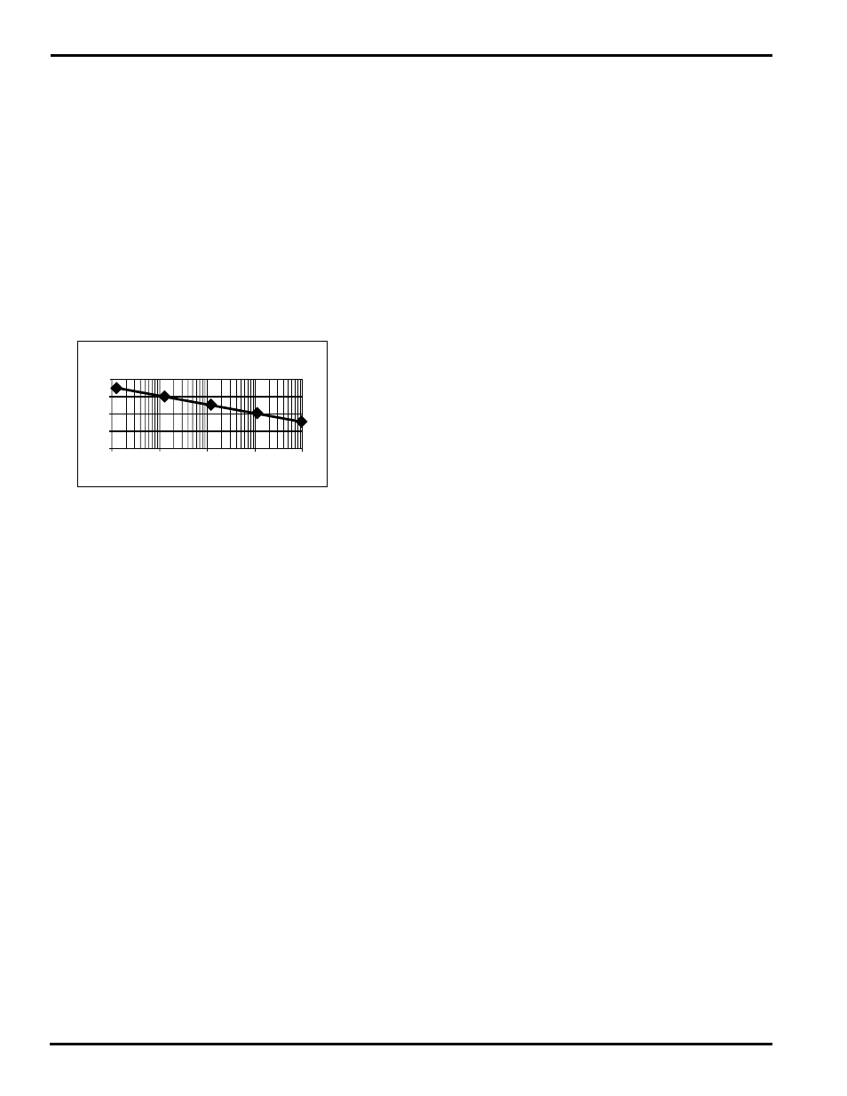
ITP as function of Conductivity for Na Cl
mS/cm
pH
8
6
4
2
0
0,01 0,1 1 10 100
Fig. 15 ITP Curve
The default setting for the Isopotential point is 0 mV
at 7.00 pH, because most manufacturers of Glass
electrodes use 7 pH as internal fill solution. The PH18
differential sensor has two measuring elements: one
pH element which has an Isopotential pH value of 1 pH
and one pNa element, which has an Isopotential pNa
value of –2. The Isopotential pH value of the differential
sensor depends on the Salt concentration. It is
recommended to set the ITP as a function of the
Conductivity according to the graph.
5-3. SLOPE
The default setting for SLOPE is 100% of theoretical
value, which is 59,16 mV/pH@25°C. It is only possible
to calibrate the SLOPE, if pH buffers are used with
identical salt concentration. These buffers are not
commercially available, so it is recommended not to
perform a SLOPE calibration, but leave the analyzer
in its default settings. It is however recommended
to perform a regular SLOPE check to verify proper
functioning of the sensor.
5. CALIBRATION