Wiring to the ph analyzer – Yokogawa SC25V User Manual
Page 9
9
IM12B6J1-40E-E
4. WIRING TO THE PH ANALYZER
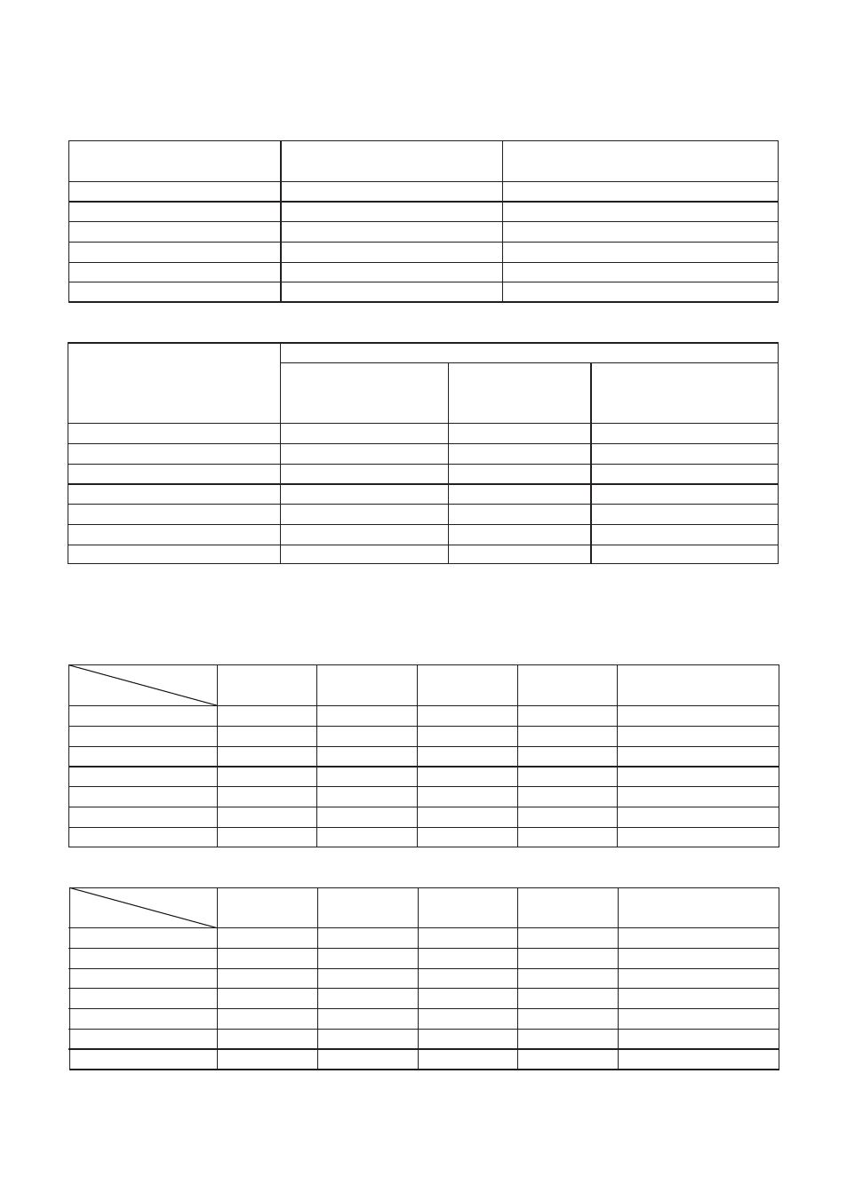
4.1 Cable marking and pin allocation
Signal description
VP connector
Cable Wire Colour
(Using WU10-V-S)
pH
A
Transparent (core coax)
pH-shield
C
Black
Reference
B
Brown (shield coax)
Liquid earth
D
Yellow (cable shield)
Temp -1
E
Red
Temp -2
F
Blue
4.2 Instrument connection of sensor
Instrument Terminal for Measurement
pH
pH&ORP
ORP only
pH-compensated
Signal description
pH&rH
ORP
pH
15
-
13
pH-shield
16
-
17
Reference
13
13
-
Liquid earth / (ORP)
14
15
15
Temp -1
11
11
11
Temp -2
12
12
12
Jumper
-
13-14
14-15
The settings for the pH instruments should follow the instruction Manual of the instrument
The following tables summarize these settings:
4.3 Instrument connection settings for PH402G and PH202G(S)
Function
pH
pH compensated
Setting
(default)
pH&ORP
pH&rH
ORP
ORP
code 01
0(pH)
0(pH)
0(pH)
1(ORP)
1(ORP)
code 02
0(off)
1(ORP)
2(rH)
0(off)
0(off)
code 03
1.1.1
1.1.1
1.1.1
0.0.1
0.0.1
code 04
0.0.1
0.0.1
0.0.1
0.0.1
1.1.1
code 31
0
2
2
Jumper input 1
no
no
no
yes
yes
Jumper input 2
yes
yes
yes
yes
no
4.4 Instrument connection settings for PH150, PH450 and FLXA21
Function
pH
pH compensated
Setting
(default)
pH&ORP
pH&rH
ORP
ORP
sensor setup
pH
pH + ORP
pH + ORP
ORP
ORP
measurement setup
pH + ORP
pH+rH
Impedance settings
input 1
High
High
High
Low
Low
input 2
Low
Low
Low
Low
High
jumper input 1
no
no
no
yes
yes
jumper input 2
yes
yes
yes
yes
no