1 loop confi guration, 2 wiring installation – Yokogawa EJA115 User Manual
Page 26
<5. Wiring>
24
IM 01C22A01-01E
5.3.1 Loop
Confi guration
Since the DPharp uses a two-wire transmission system,
signal wiring is also used as power wiring.
DC power is required for the transmitter loop. The
transmitter and distributor are connected as shown below.
For details of the power supply voltage and load
resistance, see Section 5.6.
(1) General-use Type and Flameproof Type
Hazardous Location
Non-hazardous Location
Transmitter terminal box
Distributor
(Power supply unit)
Receiver
instrument
F0504.ai
–
+
Figure 5.3
Connection between Transmitter and
Distributor
(2) Intrinsically
Safe
Type
For intrinsically safe type, a safety barrier must be
included in the loop.
Hazardous Location
Non-hazardous Location
Transmitter terminal box
Distributor
(Power supply unit)
Receiver
instrument
Safety barrier
F0505.ai
–
+
Figure 5.4
Connection between Transmitter and
Distributor
5.3.2 Wiring
Installation
(1) General-use Type and Intrinsically Safe
Type
Make cable wiring using metallic conduit or waterproof
glands.
• Apply a non-hardening sealant to the terminal box
connection port and to the threads on the fl exible
metal conduit for waterproofi ng.
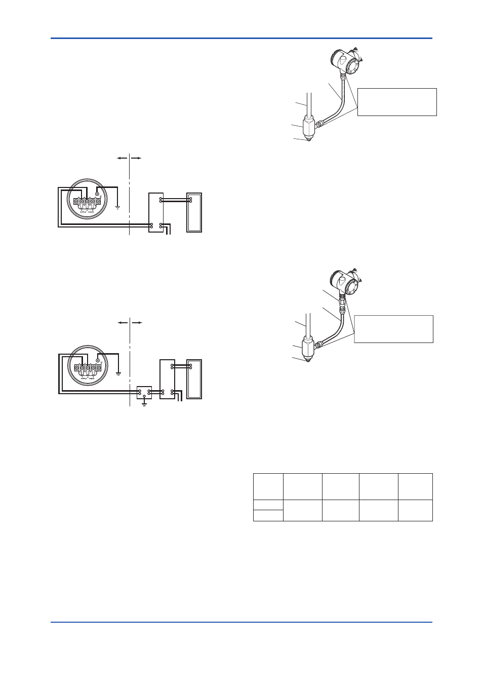
F0506.ai
Flexible metal conduit
Wiring metal
conduit
Tee
Drain plug
Apply a non-hardening
sealant to the threads for
waterproofing.
Figure 5.5
Typical Wiring Using Flexible Metal
Conduit
(2) Flameproof
Type
Wire cables through a fl ameproof packing adapter, or
using a fl ameproof metal conduit.
Wiring cable through fl ameproof packing adapter.
• Apply a non-hardening sealant to the terminal box
connection port and to the threads on the fl ameproof
packing adapter for waterproofi ng.
Flameproof packing
adapter
Flexible metal conduit
Wiring metal
conduit
Tee
Drain plug
Apply a non-hardening
sealant to the threads for
waterproofing.
F0507.ai
Figure 5.6
Typical Cable Wiring Using Flameproof
Packing Adapter
• Measure the cable outer diameter in two directions to
within 1 mm.
• Calculate the average of the two diameters, and use
packing with an internal diameter nearest to this value
(see Table 5.1).
Table 5.1
Flameproof Packings and Applicable
Cable Outer Diameters
Optional
Code
Wiring Port
Thread
Diameter
Applicable
Cable OD
(mm)
Identifying
Mark
Part
Number
G11
G 1/2
8 to 10
10.1 to 12
16
16
8-10
10-12
G9601AM
G12
• Mounting
fl
ameproof packing adapter body to conduit
connection (see Figure 5.7)
1) Screw the fl ameproof packing adapter into the
terminal box until the O-ring touches the wiring port
(at least 6 full turns), and fi rmly tighten the lock nut.