Installation instructions – Toxalert GVU-CO2 User Manual
Page 3
INSTALLATION INSTRUCTIONS
1. INSTALLATION (For specific details see sensor manual)
Locate a mounting location away from direct fresh air intakes,
and mount vertically on wall or support column approxi-
mately 3 to 6 feet above floor. Refer to figures 1 and 2; Table 1
and 2 and installation instructions in GVU series control unit
data sheet and install the GVU-CO
2
sensor as follows.
2. COVER REMOVAL
To open the Model GVU-CO
2
, use a coin in the slot on the
bottom to release the snap. Lift the cover up slightly to disen-
gage the closure and remove cover with a downward motion
to clear the catch at the top of the unit.
The locations of controls and terminals on the main circuit
board are shown in Figure 2.
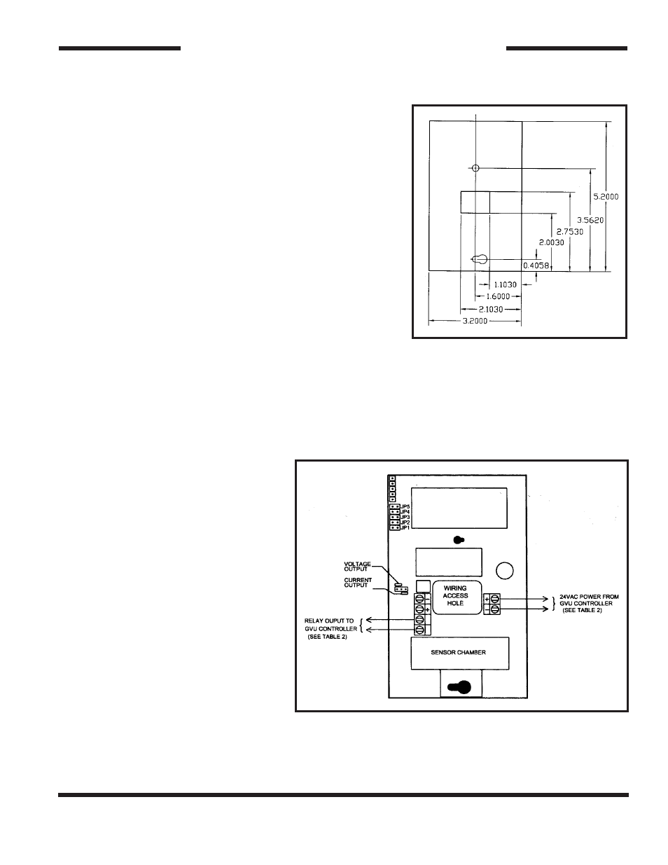
3. MOUNTING
The Model GVU-CO
2
is designed for flush mounting with two
fasteners. The locations of the mounting points
(shown in Figure 1) allow direct mounting on a standard
simplex (single circuit) junction box. There is a wiring cutout in the center of the unit near the terminal
strips.
4. SENSOR WIRING
WARNING: To prevent fire or shock
hazard, turn off power source to control
unit before making connections. Comply
with all local building codes and ordi-
nances.
NOTE: Refer to Figure 2 and Tables 1
and 2. Use shield cable to interconnect
sensor and control unit if metal conduit
is not used, or if conduit also contains
AC wiring.
1.)
Measure distance between sensing
unit and control unit and select
proper wire or larger wire from
Table 1.
2.)
Run wiring between control and
sensing unit and into enclosure
through access holes. Connect wires
from terminal blocks in sensing unit to control unit per Table 2 and GVU series control unit data
sheet.
TOXALERT INTERNATIONAL, INC.,
P.O. BOX 159, MOUND, MINNESOTA 55364 (952) 472-4541 FAX (952) 472-4960
Visit our website at www. toxalert. com
Figure 1:
Model GVU-CO
2
Mounting Dimensions
Figure 2:
Model GVU-CO
2
Component Locations