Installation instructions, Specifications – Toxalert GVU-VOC User Manual
Page 2
• Type: Metal semi conductor
• Input voltage: 20- 30VAC from GVU controller
• Operating Temperature: 32º to 104ºF (0-40ºC)
• Display: 5 indicaators ok, low, mid, high
• Sample Method: Diffusion
• Supply Current: 220 MA(max)
• Operating Humidity: 0-85% non-condensing
• Enclosure: AE wall mount
2.75”W x 4.65”H x 1.25”D
(70 x 118 x 32mm)
SPECIFICATIONS
TOXALERT INTERNATIONAL, INC.,
P.O. BOX 159, MOUND, MINNESOTA 55364 (952) 472-4541 FAX (952) 472-4960
Visit our website at www. toxalert. com
INSTALLATION INSTRUCTIONS
1. INSTALLATION
For best operation, locate a mounting location away from
direct fresh air intakes, doors and supply diffusers and
mount vertically on wall or support column approximately 5
to 6 feet above floor. An alternate location is in the ceiling
space of facilities with top discharge diesel vehicles. Refer to
figures 1 and 2; Table 1 and 2 and installation instructions in
GVU series control unit data sheet and install the GVU-
VOC sensor as follows.
2. COVER REMOVAL
Screw set-screw in bottom of cover in (clockwise) and
remove cover.
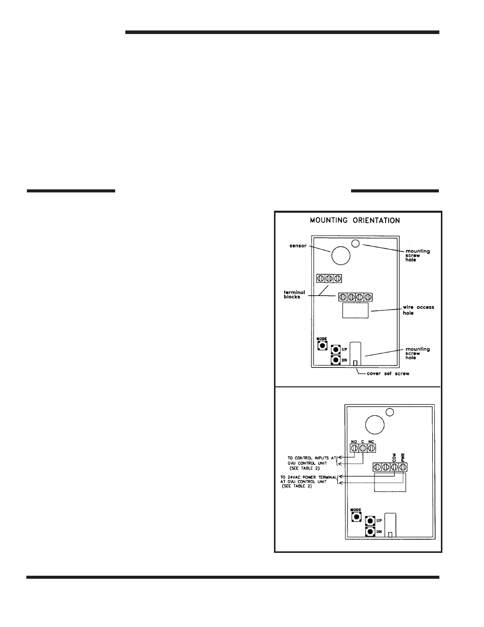
3. MOUNTING
The sensor has mounting provisions to install directly on a
standard electrical box.
4. SENSOR WIRING
WARNING: To prevent fire or shock hazard, turn
off power source to control unit before making
connections. Comply with all local building codes and
ordinances.
NOTE: Refer to Figure 2 and Tables 1 and 2. Use shield
cable to interconnect sensor and control unit if metal con-
duit is not used, or if conduit also contains AC wiring.
1.)
Measure distance between sensing unit
and control unit and select proper wire or larger wire
from Table 1.
Figure 1:
Figure 2: