Specifications, Installation instructions – Toxalert GVU-1D User Manual
Page 2
SPECIFICATIONS
• Automatic fan run upon power restoration
• Input power: 120VAC, 60 Hz, 1A (fused)
• Relay contacts: 24VAC, 2A resistive, 1.5A inductive
• Timers: 30 second delay on
Min. Fan Run Time 1-8 minutes
Hourly Fan Run: 0-8 minutes
• Enclosure:
Nema 1 standard, others available
Dimensions: 12”H x 12”W x 4”D
(305mm x 305mm x 102mm)
Finish: Gray enamel
Weight: 8 lbs. (3.6kg)
INSTALLATION INSTRUCTIONS
1. INTRODUCTION
Your TOXALERT ventilation control system incorpo-
rates the latest in solid state technology to give you
maximum reliability and performance. The system
alarm setpoint can be adjusted to activate fans upon
detection of an unsafe gas concentration such as carbon
monoxide, carbon dioxide, diesel smoke. In addition, a
user definable hourly repeat cycle is provided, allowing
time based, as well as concentration based fan activa-
tion. In both modes of fan control, the “on “ time is
user adjustable from 1 to 8 minutes in one minute
increments. For optimum performance, install, burn-in,
and check out your TOXALERT system exactly as
instructed. If your TOXALERT can’t be calibrated or
fails checkout, please contact your local representative
or TOXALERT International for servicing.
2. INSTALLATION
Locate a mounting location for the sensor away from
direct fresh air intakes, exhaust and/or supply fans, and
mount vertically on wall or support column normally 5
to 6 feet above floor (NO
2
and CO
2
sensor height may
differ per application). Mount GVU-VOC sensor in
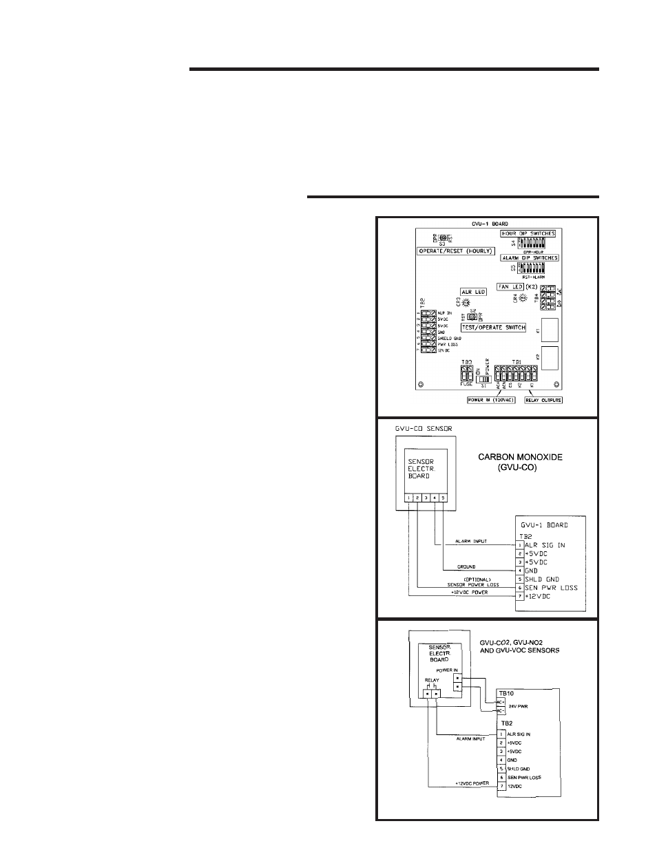
ceiling. Refer to figs. 1, 2 and 3, to install and connect
the TOXALERT control unit and sensors as following.
(Please refer to job specific documentation for more
detailed wiring options).
CONTROL UNIT-
1) Unlock and open enclosure cover.
2) If necessary, cut access holes for wiring in enclosure
sides directly opposite terminal block TB2 and
slightly below terminal block TB1. First, remove the
four screws that secure chassis plate to enclosure
and then carefully remove plate and attached circuit
board; cut holes and remove metal chips from enclo-
sure.
3) Mount enclosure with four screws.
4) Reinstall and secure chassis plate to enclosure with
the four screws
SENSORS-
Please refer to applicable sensor data sheets
for mounting directions.
FIG. 1
FIG. 3
FIG. 2