Da c b – Pfister A40-LNFCA User Manual
Page 2
English: Thank you for purchasing this Price Pfister
product. All Price Pfister products are carefully engineered,
and factory tested to provide long trouble-free use under
normal conditions. This product is easy to install using
basic tools and our easy to follow illustrated instructions. If
you have any questions regarding this product, see info on
previous page.
1 BEFORE PROCEEDING
WARNING: Read all the instructions completely before
proceeding. Price Pfister recommends calling a professional
if you are uncertain about installing this product!
This product should be installed in accordance with all local
and state plumbing and building codes.
2 SHUT OFF WATER SUPPLY
Locate water supply inlets and shut off the water supply
valves. These are usually found under the sink or near the
water meter. If you are replacing an existing faucet, remove
the old faucet from the sink and clean the sink surface
thoroughly.
3 ASSEMBLY INSTRUCTIONS
If operating pressures exceed 5 BAR (75 PSI), the use of a
pressure reducer is recommended. Before proceeding with
the assembling, we advise to clean the hot and cold water
tubes, in order to avoid build-up of dirt that could compromise
the functioning of the faucet.
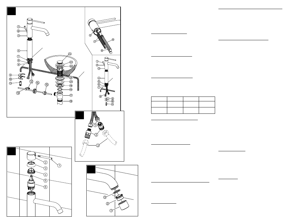
4 FAUCET INSTALLATION (Fig.A)
Assemble the threaded pins (7) and the supply tubes (8) on
the faucet body (3). Place the extension tube (4), the base
ring (5) and the O-ring (6), then insert the faucet in the hole of
the sink. Verify the correct position of the O-ring (6). Slip the
C-washer (9) and the flange (10) in the threaded pin (7), then
secure the faucet by tightening the nuts (11).
5 DRAIN MOUNTING (Fig.A)
Insert the drain (23) with the tapered seal (22) in the waste
hole (if necessary use sealant between drain and sink), then
fix using the nut (19) placing washer (21) and flange (20) in
between. Screw the vertical sleeve (16) to the waste body
(17) and all this to the drain (23), placing the washer (18) in
between. Place the ball rod (13) positioning the round piece
(15) as shown in the figure, then fix with the nut (14). Insert the
control rod (2) with the knob (1) in the faucet body, connect
it to the waste rod with the clamp (12) and then regulate the
run of the drain plug (24).
6 WATER SUPPLY CONNECTIONS (Fig.B)
Connect water supply Lines (1) to Faucet Inlets (2). Hot
water supply lines go into left inlet. Cold water supply lines
go into right inlet (The use of stopcocks with filter (3) is highly
recommended). (Supply lines are not included.) Please follow
manufacturer’s instructions when installing supply lines.
7 UNIT START UP
Turn on hot and cold water supplies, and check for leaks
above and below the sink.
CAUTION: Maintenance
DISASSEMBLY
1. Replacement parts may be available at the store where you
purchased your faucet.
2. When replacement parts are not available, please write or
call Price Pfister Consumer Service.
3. Always turn off water and relieve pressure before
working on your faucet.
NOTE: Trim Care
Cleaning Instructions:
For all handles and decorative finishes, use only a soft damp
cloth to clean and shine. Use of polish, detergents, abrasive
cleaners, organic solvents or acid may cause damage. Use of
other than a soft damp cloth will nullify our warranty!
Special Trim:
Trim products which contain porcelain or other similar
substance are not acceptable for public areas or Commercial
use. Installation of Said Trim is at Users Risk!
8 REPLACEMENT OF THE CARTRIDGE (Fig.C)
(close the main water supply) Unscrew the lever (1), take out
the handle (2), unscrew the cap (3) and the locking nut (4),
then take out the cartridge (6). Unscrew the lever holder (5)
and mount it on the new cartridge. To assemble, proceed in
reverse order, mind to clean the surfaces in contact with the
sealing washers. Close the nut (4) in such a way to grant the
sealing and in the meantime to allow that the handle turns
smoothly.
9 CLEANING THE AERATOR (Fig.D)
It is advisable to periodically clean the aerator, in order to
avoid build-up of dirt and limestone, which in time could
gradually limit the water flow. To disassemble the aerator
(1), unscrew it and clean the filter (2) from all impurities,
reassemble by proceeding in the reverse order making sure
the gasket (3) is correctly placed.
Supply
Suggested
Maximum
Minimum
Hot Water
Temperature
65 Cº (150ºF)
80 Cº (175ºF)
15 Cº (60ºF)
Operating
Pressure
3 BAR (44PSI)
5 BAR (73PSI)
0.5 BAR (7PSI)
D
A
C
B
HOT
COLD