Pfister A09-AT1C User Manual
Page 2
English: Thank you for purchasing this Price Pfister
product. All Price Pfister products are carefully engineered,
and factory tested to provide long trouble-free use under
normal conditions. This product is easy to install using basic
tools and our easy to follow illustrated instructions. If you
have any questions regarding this product, see info on
previous page.
1 BEFORE PROCEEDING
WARNING: Read all the instructions completely before
proceeding. Price Pfister recommends calling a professional
if you are uncertain about installing this product!
This product should be installed in accordance with all local
and state plumbing and building codes.
2 SHUT OFF WATER SUPPLY
Locate water supply inlets and shut off the water supply
valves. These are usually found under the basin or near the
water meter. If you are replacing an existing bidet, remove
the old bidet from the basin and clean the basin surface
thoroughly.
3 ASSEMBLY INSTRUCTIONS
If operating pressures exceed 5 BAR (~75 PSI), the use of a
pressure reducer is recommended. Before proceeding with
the assembling, we advise to clean the hot and cold water
tubes, in order to avoid build-up of dirt that could compromise
the functioning of the bidet.
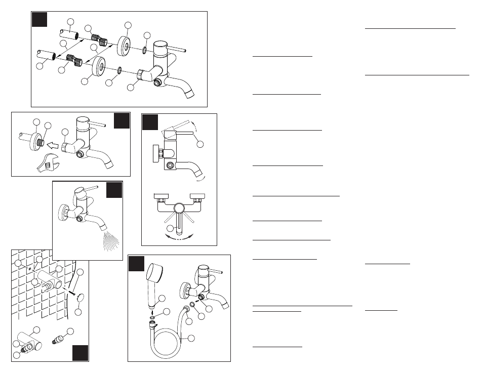
4 WIDTH DIMENSIONS (Fig.A)
The Eccentric S-Adapter (1) will accommodate a range
of width dimensions (2) from 5 1/4” to 6 1/2” [133.35mm
to 165.10mm]. S-Adapter center line (3) must be 5 7/8”
[149.23mm].
5 S-ADAPTER INSTALLATION (Fig.A)
Apply plumber’s tape to all threaded nipples according to
manufacturer’s instructions. Hand tighten the S-Adapters (1)
to inlet pipes (4) projecting through the wall.
6 FAUCET ASSEMBLY (Fig.A)
Insert Washers (5) into Union Nuts (6). Hand tighten Wall
Cap (7) to S-Adapter (1).
7 FAUCET INSTALLATION (Fig.B)
Wrench tighten Union Nuts (1) to S-Adapters (2). Adjust Wall
Cap (3) so that it sits flush with the finished wall.
8 VALVE FUNCTION (Fig.C)
By lifting the Lever Handle (1) up, the valve will be activated
allowing water to flow. The water flow will increase by
continuing to lift up the Lever Handle (1). By rotating the
Lever Handle counter-clockwise, the water temperature will
decrease to cold flow only. By rotating the Lever Handle
clockwise, the water temperature will increased to hot flow
only.
9 TUB SPOUT AND HAND HELD SHOWER
APPLICATION (Fig.F)
Water flow activated by the lever will flow from the tub spout
by default. To activate the hand held shower, depress the
button (7) on the right side of the spout base. This will divert
water flow from the tub spout to the hand held shower. The
valve funtions described in Step 8 still apply.
10 FLUSHING (Fig.D)
After installation is complete, turn water supply valves on and
turn faucet on. Allow both hot and cold water to run at least
CAUTION: Maintenance
DISASSEMBLY
1. Replacement parts may be available at the store where you
purchased your bidet.
2. When replacement parts are not available, please write or
call Price Pfister Consumer Service.
3. Always turn off water and relieve pressure before
working on your bidet.
NOTE: Trim Care
Cleaning Instructions:
For all Handles and decorative finishes, use only a soft damp
cloth to clean and shine. Use of polish, detergents, abrasive
cleaners, organic solvents or acid may cause damage. Use of
other than a soft damp cloth will nullify our warranty!
Special Trim:
Trim products which contain Porcelain or other similar
substance are not acceptable for public areas or Commercial
use. Installation of Said Trim is at Users Risk!
one minute each until all foreign matter has cleared the line.
While water is running, check for leaks.
11 WALL HOOK INSTALLATION (Fig.E)
Drill one
1
/
4
” Dia. Hole (1). If installing into a stud, drill a one
1
/
8
” Dia. hole and do not use the anchor (2). Insert anchor (2)
into hole (1) and tap flush with wall. Place wall mount (3) onto
wall and insert mounting screw (4) through wall mount hole
(1) and tighten until wall mount (3) is flush with the wall. (Do
Not Over Tighten!) Insert front cover (5) into Wall Mount (3).
Shower hose (6) hangs on wall mount hook (7) as shown.
12 HAND HELD SHOWER ASSEMBLY (Fig.F)
Be sure that rubber washers (1 & 2) are inserted into the
adaper piece (3) and inlet fitting (4). Connect Flexible Hose
(5) to the bottom of faucet as shown. Thread Shower Arm (6)
into Flexible Hose (5).
A
B
C
E
D
F
1
4
5
7
1
1
1
2
3
2
3
1
4
6
5
7
HOT
OPEN
COLD
1
4
2
3
3
7
7
6
6
5
2
1
3
5
6
4