Dc b, Hot shower cold – Pfister A08-AS1C User Manual
Page 2
English: Thank you for purchasing this Price Pfister
product. All Price Pfister products are carefully engineered,
and factory tested to provide long trouble-free use under
normal conditions. This product is easy to install using basic
tools and our easy to follow illustrated instructions. If you
have any questions regarding this product, see info on
previous page.
1 BEFORE PROCEEDING
WARNING: Read all the instructions completely before
proceeding. Price Pfister recommends calling a professional
if you are uncertain about installing this product!
This product should be installed in accordance with all local
and state plumbing and building codes.
2 SHUT OFF WATER SUPPLY
Locate water supply inlets and shut off the water supply
valves. These are usually found under the sink or near the
water meter. If you are replacing an existing faucet, remove
the old faucet from the sink and clean the sink surface
thoroughly.
3 ASSEMBLY INSTRUCTIONS
If operating pressures exceed 5 BAR (~75 PSI), the use of a
pressure reducer is recommended. Before proceeding with
the assembling, we advise to clean the hot and cold water
tubes, in order to avoid build-up of dirt that could compromise
the functioning of the valve.
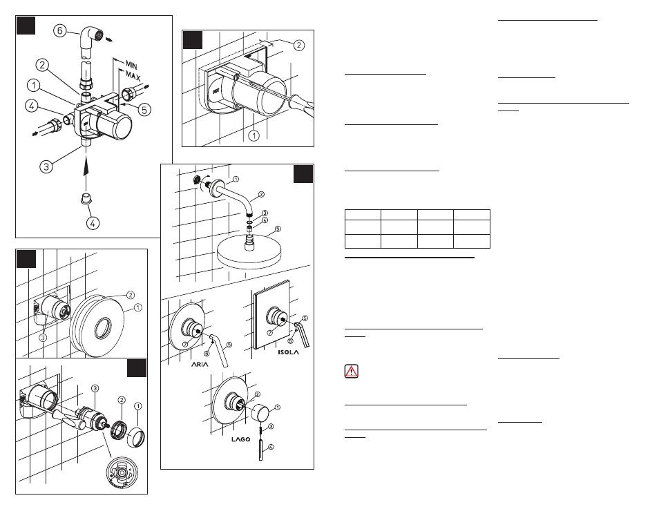
4 PRESSURE BALANCE INSTALLATION
(Fig.A) Place the valve body (1) into the wall, with the shower
outlet facing the up. Then connect the hot water supply to the
left inlet and the cold water supply to the right inlet.
(Fig.B) The embedded depth (2) of the wall (coating
included) must be within the tolerance set by the thickness
by the plastic cover (1). Carry out the finishing of the wall
and remove the plastic cover (1) using a screwdriver remove
the screws.
5 SHOWER ONLY OUTLET CONNECTIONS
(Fig.A)
Connect shower outlet pipe (2) to valve body (1). Plug bottom
outlet (3) with pipe cap or plug (4). Connect pipe elbow (6)
(not included) to end of the pipe.
WARNING Iron Pipe Connections: When attaching
threaded fittings, use thread sealant or PTFE Plumber’s tape
according to manufacturer’s instructions.
6 TRIM FLANGE ATTACHMENT (Fig.C)
Position valve flange (1) with the gasket (2) onto the valve
body (3) and slide flange until flush with wall.
7 SHOWER ARM AND HEAD INSTALLATION
(Fig.D)
Insert the longer end of shower arm (2) through the shower
arm flange (1). Apply PTFE plumber's tape to both ends of
shower arm (2) according to manufacturer's instructions.
Screw the end of shower arm (2) into pipe elbow inside the
wall. Slide shower arm flange (1) tight to the wall. Screw the
shower head (5) to the shower arm (2), with the washer (3)
and aerator (4) placed (9) in between.
CAUTION: Maintenance
DISASSEMBLY
1. Replacement parts may be available at the store where you
purchased your faucet.
2. When replacement parts are not available, please write or
call Price Pfister Consumer Service.
3. Always turn off water and relieve pressure before
working on your faucet.
NOTE: Trim Care
Cleaning Instructions:
For all Handles and decorative finishes, use only a soft damp
cloth to clean and shine. Use of polish, detergents, abrasive
cleaners, organic solvents or acid may cause damage. Use of
other than a soft damp cloth will nullify our warranty!
Special Trim:
Trim products which contain Porcelain or other similar
substance are not acceptable for public areas or Commercial
use. Installation of Said Trim is at Users Risk!
8 LEVER ATTACHMENT (Fig.D)
FOR LAGO SERIES: Place handle hub (1) on valve stem (2)
and secure with grub screw (3) (do not over tighten). Then
screw lever (4) on to back end of grub screw (do not over
tighten).
FOR ARIA AND ISOLA SERIES: Place lever (5) on valve
stem (6). Then affix lever screw (7).
9 UNIT START UP
Turn on hot and cold water supplies, and check all connections
for leaks.
10 REPLACEMENT OF THE CARTRIDGE
(Fig.E)
(close the waterworks) If it becomes necessary to replace
the cartridge, reverse the steps of Fig.E then Fig.C. With
a screwdriver, close the supply stops with a 90° rotation.
Unscrew the cap (1), the nut (2) and take out the cartridge
(3). To assemble proceed in reverse order. Pressure balance
faucets are provided with a temperature reducer device to
prevent burns. For suggested conditions (pressure and hot/
cold water temperature), the temperature limit is at 100°F
max. If you need to change this limit, turn the nut clockwise to
get colder temperature and counterclockwise to get warmer
temperature.
Supply
Suggested
Maximum
Minimum
Hot Water
Temperature
65 Cº (150ºF)
80 Cº (175ºF)
15 Cº (60ºF)
Operating
Pressure
3 BAR (44PSI)
5 BAR (73PSI)
0.5 BAR (7PSI)
E
A
HOT
Shower
COLD
D
C
B