En g l is h english, Installation steps – Pfister R89-9THK User Manual
Page 2
E
N
G
L
IS
H
ENGLISH
ENGLISH
4
5
3
INSTALLATION STEPS
6
Thank you for purchasing this Price Pfi ster product. All Price Pfi ster products are carefully engineered, and factory tested to provide long trouble-free use under normal
conditions. This product is easy to install using basic tools and our easy to follow illustrated instructions. If you have any questions regarding your product installation
call 1-800-Pfaucet (1-800-732-8238).
1 BEFORE PROCEEDING
WARNING: Read all the instructions completely before proceeding.
Price Pfi ster recommends calling a professional if you are uncertain about
installing this product!
This product should be installed in accordance with all local and state plumbing
and building codes.
WARNING: This product has been designed for use with the Price Pfi ster
0T8-410 series thermostatic valve. It will not work with any other product.
Please review the 0T8-410 valve installation instructions before installing this
product.
2 SHUT OFF WATER SUPPLY
Locate water supply inlets and shut off the water supply valves. These are
usually found near the water meter. If you are replacing an existing unit, remove
the old unit and clean the mounting surface thoroughly.
3 TOOLS RECOMMENDED
• PTFE plumber's tape or thread sealant
• Phillips head screwdriver
• Adjustable wrench • Pipe wrench
• Flashlight
• Cloth
Your installation may require additional tools.
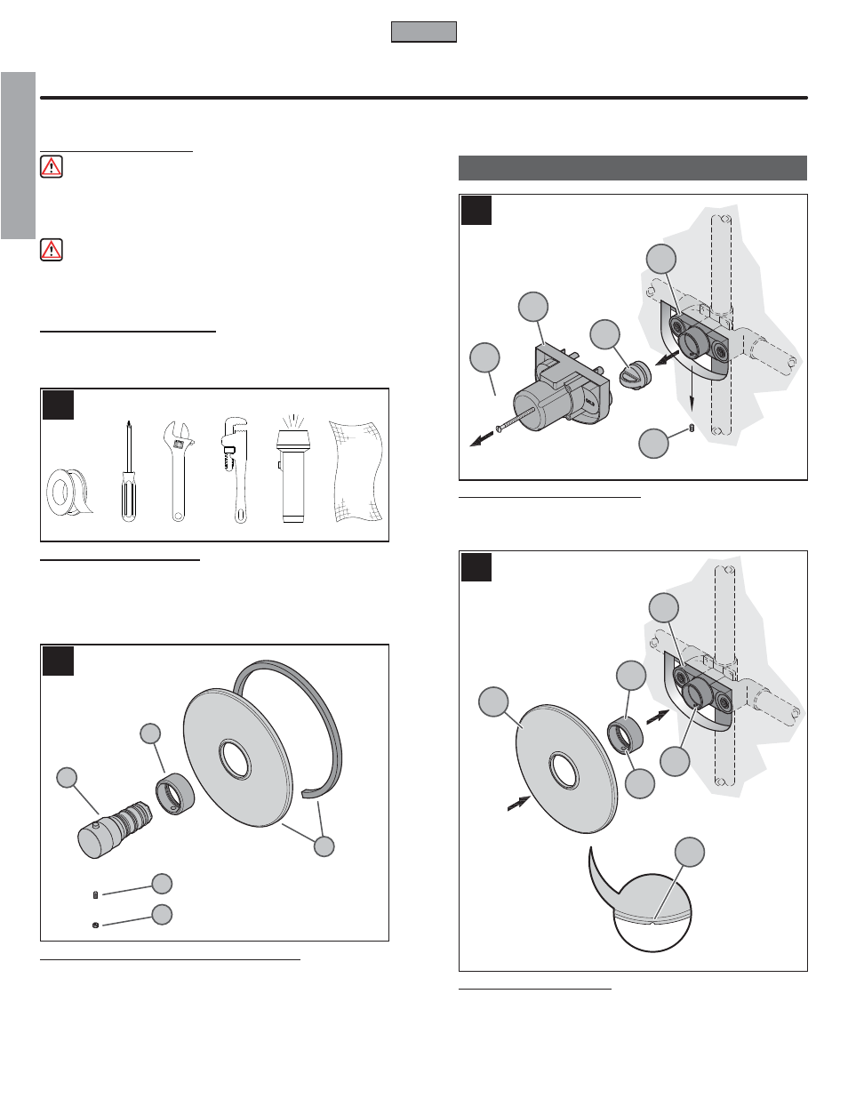
4 CHECKING THE CONTENTS OF THE BOX
Upon opening the box, check to ensure that all of the following items are
included.
A Gasket & Trim Flange
B Retainer Sleeve
C Temperature Knob
D Set Screw
E
Button
If any of these items are missing, please contact Price Pfi ster Consumer Service
at 1-800-Pfaucet (1-800-732-8238).
6 FLANGE ATTACHMENT
Place Sleeve (6A) onto Valve Body (6B). Position Sleeve (6A) so that Hole
(6C) is aligned with Valve Hole (6D).
Slide Flange (6E) onto Sleeve (6A) with Drain Hole (6F) at the bottom until is
snug to fi nished wall surface.
5 PLASTERGUARD REMOVAL
Remove Screws (5A), and Plasterguard (5B) from Valve Body (5C). Remove
Set Screw (5D) from Valve Body (5C) and save. Remove Plug (5E) from
Valve Body (5C).
2
5A
5B
5C
5D
5E
6A
6B
6D
6C
6E
6F
A
B
D
E
C