En g l is h english, Stop – Pfister 016-300K User Manual
Page 2
E
N
G
L
IS
H
ENGLISH
ENGLISH
4
2
3
5
6
7
Thank you for purchasing this Price Pfi ster product. All Price Pfi ster products are carefully engineered, and factory tested to
provide long trouble-free use under normal conditions. This product is easy to install using basic tools and our easy to follow
illustrated instructions. If you have any questions regarding this product, call 1-800-Pfaucet (1-800-732-8238).
1 BEFORE PROCEEDING
WARNING: Read all the instructions completely before proceeding. Price Pfi ster
recommends calling a professional if you are uncertain about installing this product!
This product should be installed in accordance with all local and state plumbing and
building codes.
2 SHUT OFF WATER SUPPLY
Locate water supply inlets and shut off the water supply valves. These are usually found
under the sink or near the water meter. If you are replacing an existing faucet, remove
the old faucet from the sink and clean the sink surface thoroughly.
3 TOOLS RECOMMENDED
• Plumber's putty
• Slotted screwdriver
• Pliers
• Adjustable wrench
• Flashlight
• Cloth
Your installation may require new supply lines and / or shut-off valves or other additional
tools.
WALL MOUNT PACKAGE INSTALLATION
STOP
Go To Step 12
Go To Step 12
Models
16-200
Option 1:
Wall Mount Package
Installation
Go To Step 5
Go To Step 5
Models
16-300
Option 2:
Slide Bar Package
Installation
Go To Step 7
Go To Step 7
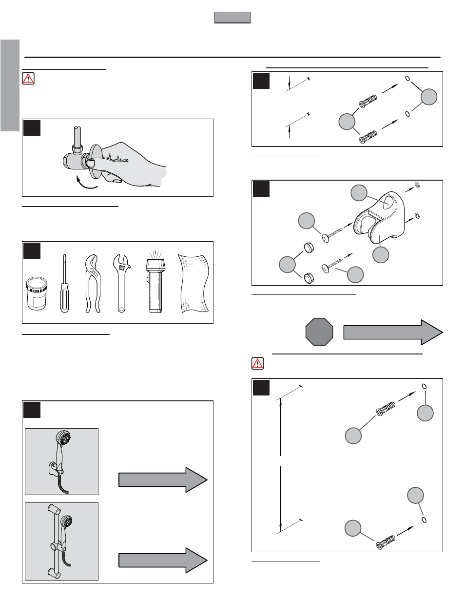
5 HOLE LOCATIONS
Determine desired location for Wall Mount and tap screw hole locations as shown. Holes
must be aligned vertically. Drill two
1
/
4
” holes. If installing into a stud, drill two
1
/
8
” hole and
do not use Anchors (5A). Insert Anchors (5A) into Holes (5B) and tap fl ush with wall.
6 WALL MOUNT INSTALLATION
Place Wall Mount (6A) onto wall and insert Mounting Screws (6B) through Wall Mount
Holes (6C) and tighten until Wall Mount (6A) is fl ush with the wall. Do Not Over Tighten!
Insert Buttons (6D) into Holes (6C).
SLIDE BAR PACKAGE INSTALLATION
7 HOLE LOCATIONS
Determine desired location for Slide Bar and tap screw hole locations as shown. Holes
must be aligned vertically. Drill two
1
/
4
” holes. If installing into a stud, drill two
1
/
8
” hole and
do not use Anchors (7A). Insert Anchors (7A) into Holes (7B) and tap fl ush with wall.
WARNING: To reduce risk of injury, Slide Bar must not be used as grab bar or
for support.
These instructions cover two different
installations
2
5A
6A
7A
5B
6D
6C
7B
7B
7A
6B
6B
2
7
/
32
”
26
3
/
4
”