En g li sh en g li sh – Pfister GT49-FE0K User Manual
Page 3
EN
G
LI
SH
EN
G
LI
SH
ENGLISH
7
8
9
10
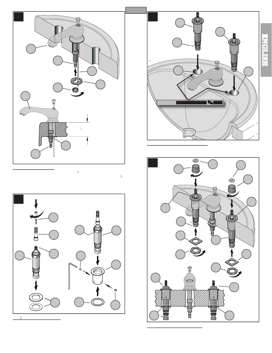
7 SECURING SPOUT
From underneath sink, place Mounting Washer (7A
77 ) onto Spout Shank (7B) and hand
tighten with Mounting Nut (7C). Align Lift Rod (7D) with slot in Mounting Washer (7A
77 ).
Be sure Spout (7E) is centered and facing forward and tighten the Mounting Nut (7C)
until Spout (7E) is fi rmly secured to sink.
8 VALVE PREPARATION
VV
Remove existing Washers (8A) from Valve Body (8E). Insert Stem Extension (8B) into
Valve Stem (8C) and secure by threading Screw Adapter (8D). Insert Valve Body (8E)
through Adapter Extension (8F). Secure with Set Screws (8G) by using a
3
/
32
// ” Allen
Wrench. Be sure Flat Surfaces (8J) from End Body (8E) are aligned with Set Screws
(8G). Do not over tighten! Place Rubber Washer (8H) onto Adapter Extension (8F).
9 VALVE BODY INSTALLATION
From above sink, insert Valve Body (9A
99 ) through Mounting Holes (9B). The HOT valve,
labeled with Red Tag (9C), should be positioned to the left side of the spout.
10 SECURING VALVE BODY
From underneath sink, place Square Washer (10A) onto Valve Shank (10B) and tighten
using Mounting Nut (10C). From above sink, thread Adapter Ring (10D) by hand into
Valve Body (10E). Place Plastic Washer (10F) into Adapter Ring (10D).
3
7A
8B
9B
10A
10A
7C
7B
7D
7E
7C
7B
7E
8A
8D
8C
8J
8F
8H
8G
8G
9A
9A
9B
9C
10C
10A
10A
10C
10D
10D
10B
10B
10E
10E
10D
10C
10C
10D
1
1
/
2
// ” Minimum
8E
8E
Recommended Hole Size 1
8
10F
10F