Watlow VPAC-BT Remote Mount Transformer User Manual
Page 2
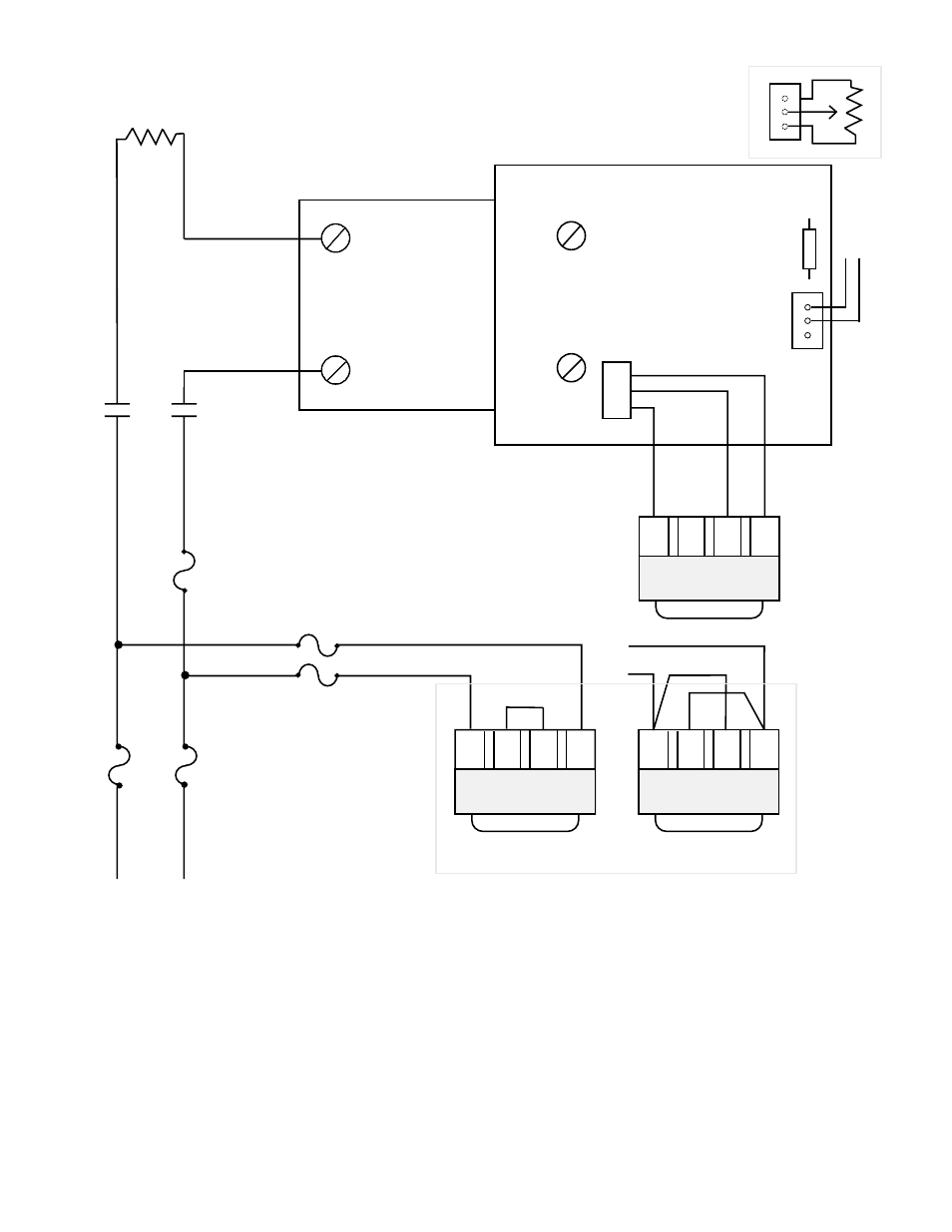
Input
Pot (+) (-)
T
ransformer Plug
R22
Zero Cross
SSR
- +
BT
8
7
6
5
4
3
2
1
4
3
2
1
Heater
Safety Contactor
if required
Semiconductor
Fuse
Branch Circuit
Fuses
T
ransformer
Fuses
Primary
T
ransformer
Connections
(bottom view)
red
black
white
black
240
V
olt
120
V
olt
Secondary
T
ransformer
Connections
(top view)
Note:
Input is 250 ohms.
For 5K input, cut R22.
Common
Positive
Pot (+) (-)
Manual Control
L1
L2
12V~(ac)
Common
(center tap)
12V~(ac)
orange
white
violet
Note:
The controls transformer must
be on the same phase as the
load. See wiring diagram.
All
hot lines to the transformer
should be fused at 1 amp with
the proper line voltage.
For manual control, a 1K
Ω
potentiometer may be connected
to the
A
T
card input terminals.
W
a
tlow offers a Manual Control
Kit, P/N 08-5362. Using this
potentiometer requires removing
the 5K
Ω
, R2 resistor for higher
impedance.
Bias and gain adjustment is
required when changing from 4-
20mA
input to a manual control
input or a voltage input.
W
iring Diagram for VP
AC-BT
Remote Mount T
ransformer
- 12LS Controller (111 pages)
- 8LS Controller (140 pages)
- 8PID Controller (55 pages)
- Addendum to EZwarePlus (50 pages)
- ANASCAN (62 pages)
- ANASOFT (95 pages)
- ANAWIN 2 (154 pages)
- ANAWIN 3 (23 pages)
- Calibrating Watlow Series 988 Family Process Controls (19 pages)
- CAS (98 pages)
- CAS200 (124 pages)
- CLS (180 pages)
- CLS200 (251 pages)
- CLS200, MLS300 and CAS200 (92 pages)
- Control Console (12 pages)
- CPC400 (230 pages)
- DIN-A-MITE Style A (9 pages)
- DIN-A-MITE Style B (14 pages)
- DIN-A-MITE Style C (22 pages)
- DIN-A-MITE Style D (9 pages)
- DIN-Mount Adapter Instruction Sheet, Rev A (1 page)
- Dual DAC (4 pages)
- EM Gateway (28 pages)
- E-Safe Hybrid Relay Rev B (4 pages)
- E-SAFE II Hybrid Power Switch (4 pages)
- EZwarePlus Programming (264 pages)
- EZ-ZONE PM (111 pages)
- EZ-ZONE PM PID (125 pages)
- EZ-ZONE PM Express Limit (34 pages)
- EZ-ZONE PM Express (35 pages)
- EZ-ZONE PM Integrated Controller (181 pages)
- EZ-ZONE RM Limit Module Rev C (127 pages)
- EZ-ZONE RMA Modul (79 pages)
- EZ-ZONE RMC (236 pages)
- EZ-ZONE RME (124 pages)
- EZ-ZONE RMH (161 pages)
- EZ-ZONE RUI/Gateway (62 pages)
- EZ-ZONE RM-Scanner-Modul (140 pages)
- EZ-ZONE ST (97 pages)
- F4 External Event Board - Rev.B (2 pages)
- HG Series Mercury Displacement Relay (6 pages)
- LogicPro (296 pages)
- Mercury Relay or MDR Retrofit (13 pages)
- MICRODIN (106 pages)
- MICRODIN (24 pages)