Dc or ac input solid state relay wiring diagram, 3 phase, 2 leg solid state relay wiring diagram, Warning – Watlow Solid State Relay (SSR) User Manual
Page 2
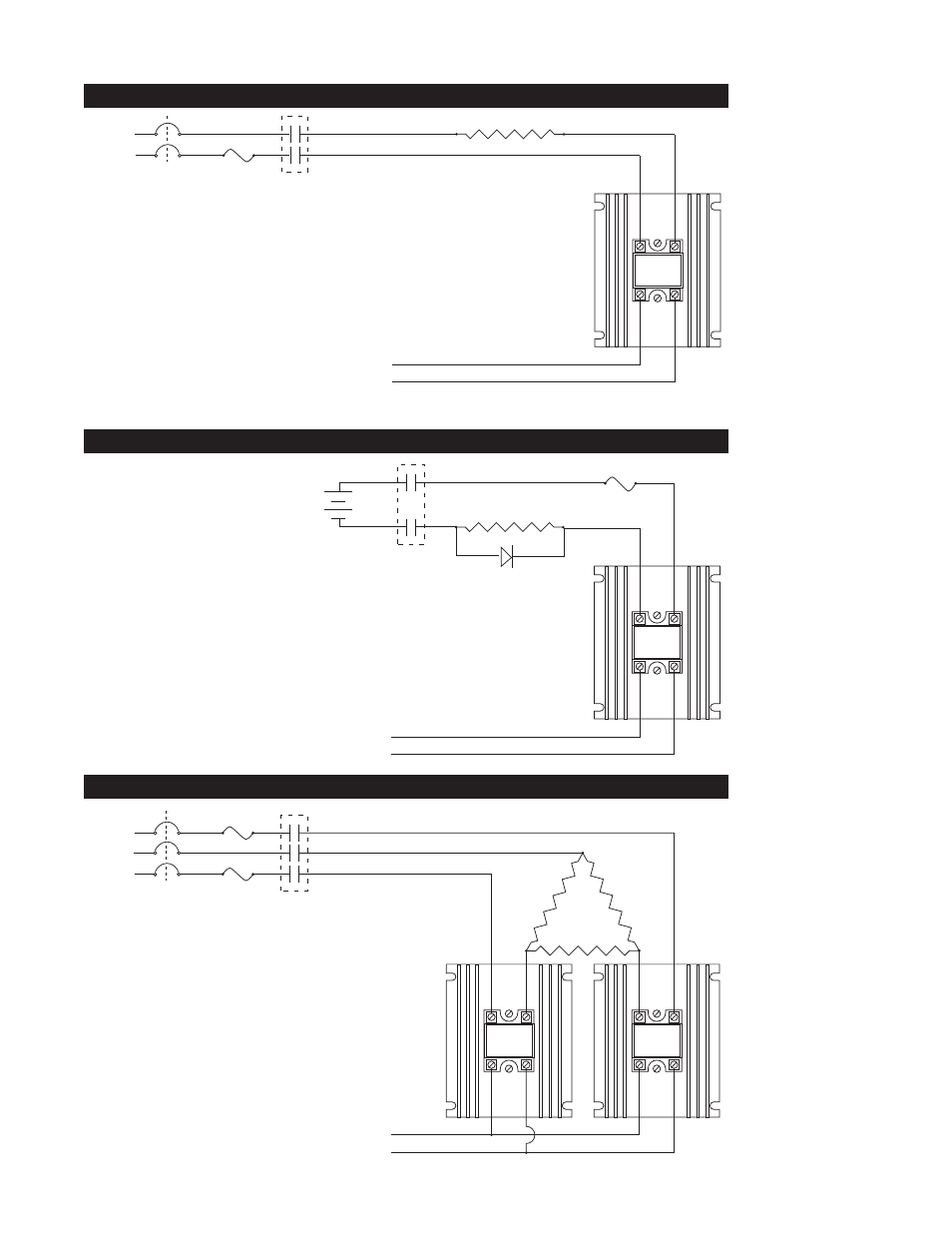
DC or AC Input Solid State Relay Wiring Diagram
Heater
Limit Control
Contacts
(If Required)
L2
L1
1
2
4
3
2
1
Semiconductor
Fuse
90-240VAC
AC Input
3-32VDC
DC Input
OR
(-)
(+)
DC Input, DC Output Solid State Relay Wiring Diagram
Heater
Limit Control
Contacts
(If Required)
1(–) (+)2
4(–) (+)3
1
1
Fuse
Open Collector
DC Input, 3-32VDC
External
DC Power
Supply
0-100 VDC
Install diode if
load is inductive
(-)
(+)
SSR-100-20A-DC1
3 Phase, 2 leg Solid State Relay Wiring Diagram
1
2
4
3
Limit Control
Contacts
(If Required)
L2
L3
L1
1
2
4
3
3 Phase
Heater
2
1
Semiconductor
Fuses
Control Input Signal
SSR Mounting and Installation Instructions
ç
1
WARNING:
Wiring must con-
form to National
Electric Code
(NEC) safety stan-
dards, as well as
locally applicable
codes. Failure to
do so could
result in personal
injury or death.
ç
2
WARNING:
Wiring examples
show L2 in
240VAC or
480VAC configu-
ration. In 120VAC
applications, L2 is
neutral and must
not be fused or
switched. Failure
to follow this
guideline could
result in personal
injury or death.
з
з
з
з
з