Input wiring, Output wiring, Thermocouple – Watlow Series 104 User Manual
Page 3: And 3-wire rtd, Electromechanical relay, form c, 8a, Solid-state relay, form a, 0.5a, Switched dc, 3■ watlow series 104 user’s manual, Figure 2b — 2- and 3-wire rtd wiring, 104 e
3
■
Watlow Series 104 User’s Manual
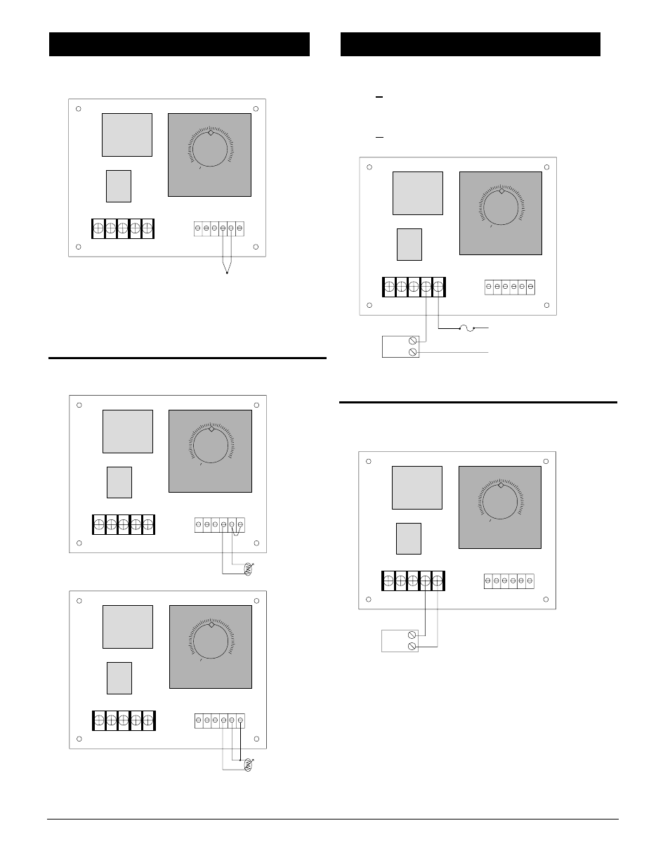
Thermocouple
Figure 2a — Thermocouple wiring.
NOTE: When an external device with a non-isolated circuit common
is connected to the switched dc output, you must use an isolated or
ungrounded thermocouple.
2- and 3-wire RTD
Figure 2b — 2- and 3-wire RTD wiring.
Electromechanical Relay, Form C, 8A
104E - _ _ _ _ - _ 00
Solid-State Relay, Form A, 0.5A
104K - _ _ _ _ - _ 000
Figure 2c — Electromechanical and solid-state relay wiring.
NOTE: NC is available only with 104E.
Switched DC
104C - _ _ _ _ - 0000
Figure 2d — Switched dc wiring.
ç
WARNING: We strongly recommend that all control loops use an
approved temperature limit for over or under temperature limit
protection. Failure to install a temperature limit for protection
where a potential hazard exists could result in damage to
equipment.
00
50
100
150
200
250
300
350
400
450
500
External
Device
DC -
DC +
00
50
100
150
200
250
300
350
400
450
500
External
Device
Fuse
L1
L2
NC NO C
Output Wiring
00
50
100
150
200
250
300
350
400
450
500
S1
S2
S3
3-wire RTD
00
50
100
150
200
250
300
350
400
450
500
S1
S2
S3
2-wire RTD
00
50
100
150
200
250
300
350
400
450
500
TC +
TC -
Input Wiring