Power wiring, Input wiring, User interface – Watlow Series 102 User Manual
Page 3: Output wiring, Thermocouple, And 3-wire rtd, Switched dc
Watlow Series 102 User’s Manual
■
3
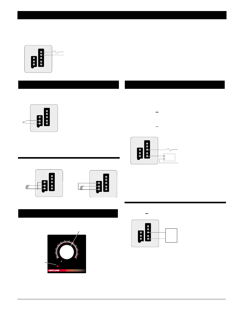
Thermocouple
Figure 3b — Thermocouple wiring.
NOTE: When an external device with a non-isolated circuit common
is connected to the switched dc output, you must use an isolated or
ungrounded thermocouple.
2- and 3-wire RTD
Figure 3c — 2- and 3-wire RTD wiring.
Figure 3d — Series 102 interface.
Electromechanical Relay, Form C without
contact suppression
3A
102 D - _ _ _ _ - _ 000
Solid-State Relay, Form A, 0.5A without contact suppression
0.5A
102 K - _ _ _ _ - _ 000
Figure 3e — Electromechanical and solid-state relay wiring.
NOTE: Switching inductive loads (relay coils, solenoids, etc.) with
the mechanical relay, switched dc or solid-state relay output options
requires use of an R.C. suppressor. Watlow carries the R.C.
suppressor Quencharc brand name of ITW Paktron, Watlow Part No.
0804-0147-0000.
Switched DC
102C - _ _ _ _ - _ 000
Figure 3f — Switched dc wiring.
ç
WARNING: We strongly recommend that all control loops use an
approved temperature limit controller for over or under temperature
limit protection. Failure to install temperature limit control
protection where a potential hazard exists could result in damage to
equipment and property and injury to personnel.
S
e
n
s
o
r
1
2
3
4
5
dc-
dc+
External
Device
Fuse
L1
L2
External
Device
C
NC
NO
S
e
n
s
o
r
1
2
3
4
5
Output Wiring
˚C
˚F
Load
102
100
150
200
250
300
350
400
450
500
550
600
50
0
50
150
200
100
250
300
315
Type J T/C
Load
Indicator
Light
Temperature Adjustment
Setpot
User Interface
S1
S3
S2
S
e
n
s
o
r
1
2
3
4
5
3-wire RTD
S1
S3
S2
S
e
n
s
o
r
1
2
3
4
5
2-wire RTD
S
e
n
s
o
r
1
2
3
4
5
TC-
TC+
Input Wiring
120VÅ
102 _ - 1 _ _ _ - 0000
230 to 240VÅ
102 _ - 2 _ _ _ - 0000
NOTE: The line voltage is specified by your model number.
Figure 3a — Power wiring.
∫
WARNING: To avoid potential electric shock, use National Electrical
Code (NEC) safety practices when wiring and connecting this unit to
a power source and to electrical sensors or peripheral devices.
All wiring and fusing must conform to the National Electric
Code and to any locally applicable codes.
ç
CAUTION: Applying incorrect line voltage may result in irreversible
damage to the controller.
Recommended fuse size: 1A
S
e
n
s
o
r
1
2
Fuse
L1
L2
3
4
5
Power Wiring