Watlow SDMA Card Shorted Solid State Relay Detector User Manual
Page 2
Load
Number of Passes of Load Wire
Current
Through Current Transformer
2 to 3 Amps
5
3 to 4 Amps
4
4 to 5 Amps
3
5 to 10 Amps
2
10 to 40 Amps
1
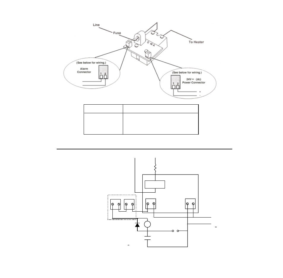
S D M A
Heater
+
-
Alarm
Coil
D1
- 24V +
1 2
1 2
Normally Closed
Contact
SW1
Momentary
Reset Switch
RYI Contacts
External Latching Relay
24V (dc) Coil
V~ (ac)
24V (dc)
(Customer Supplied)
Minimum of 21mA
supply current
(per SDMA card)
is required.
RY1
CT
Alarm
1 2
Alarm
1 2
Figure 3 - SDMA Card Wiring
Table 1 - Application of 16-0231 Current Transformer
Figure 2 - Three Dimensional View of Wiring
NOTES:
Include a flyback diode across the external
latching relay coil. See D1.
To form a logic chain alarm, place multiple
SDMA alarm outputs in series.
See also other documents in the category Watlow Sensors:
- 12LS Controller (111 pages)
- 8LS Controller (140 pages)
- 8PID Controller (55 pages)
- Addendum to EZwarePlus (50 pages)
- ANASCAN (62 pages)
- ANASOFT (95 pages)
- ANAWIN 2 (154 pages)
- ANAWIN 3 (23 pages)
- Calibrating Watlow Series 988 Family Process Controls (19 pages)
- CAS (98 pages)
- CAS200 (124 pages)
- CLS (180 pages)
- CLS200 (251 pages)
- CLS200, MLS300 and CAS200 (92 pages)
- Control Console (12 pages)
- CPC400 (230 pages)
- DIN-A-MITE Style A (9 pages)
- DIN-A-MITE Style B (14 pages)
- DIN-A-MITE Style C (22 pages)
- DIN-A-MITE Style D (9 pages)
- DIN-Mount Adapter Instruction Sheet, Rev A (1 page)
- Dual DAC (4 pages)
- EM Gateway (28 pages)
- E-Safe Hybrid Relay Rev B (4 pages)
- E-SAFE II Hybrid Power Switch (4 pages)
- EZwarePlus Programming (264 pages)
- EZ-ZONE PM (111 pages)
- EZ-ZONE PM PID (125 pages)
- EZ-ZONE PM Express Limit (34 pages)
- EZ-ZONE PM Express (35 pages)
- EZ-ZONE PM Integrated Controller (181 pages)
- EZ-ZONE RM Limit Module Rev C (127 pages)
- EZ-ZONE RMA Modul (79 pages)
- EZ-ZONE RMC (236 pages)
- EZ-ZONE RME (124 pages)
- EZ-ZONE RMH (161 pages)
- EZ-ZONE RUI/Gateway (62 pages)
- EZ-ZONE RM-Scanner-Modul (140 pages)
- EZ-ZONE ST (97 pages)
- F4 External Event Board - Rev.B (2 pages)
- HG Series Mercury Displacement Relay (6 pages)
- LogicPro (296 pages)
- Mercury Relay or MDR Retrofit (13 pages)
- MICRODIN (24 pages)
- MICRODIN (106 pages)