Wiring the serial dac, Da c, Measur ement & contr ol – Watlow SDAC User Manual
Page 2: Configuring serial dac outputs, Warnings, Pins, Serial dac, 2watlow sdac user’s guide, Warning, Figure 3 . voltage and current jumper positions
4 mm (0.2 in.)
diameter
44 mm
(1.8 in.)
76 mm
(3.0 in.)
91 mm
(3.6 in.)
8 mm
(0.3 in.)
10 mm
(0.4 in.)
138 mm (5.5 in.)
119 mm (4.7 in.)
Measur
ement
& Contr
ement
&
Contr
ol
SERIAL D
AC
+5V IN
COM IN
CLK IN
DA
TA
IN
FLASHING
=RUNNING
+ OUT
- OUT
P
IN
:
1
2
3 4
5 6
O
U
T
P
U
T
S
E
LE
C
T
C
U
R
R
E
N
T
V
O
LT
A
G
E
{
{
Po
wer Input:
5Vdc
, 300mA max.
Voltage Output:
10Vdc
, 10mA max.
Current O
utpu
t: 10V
dc, 20
mA
m
ax.
US
E C
OP
PE
R C
ON
DU
CT
OR
S O
NLY
2
WATLOW SDAC User’s Guide
Wiring the Serial DAC
The Serial DAC provides a robust analog output sig-
nal. The module converts the proprietary Serial DAC
signal from the controller’s open collector output in
conjunction with the clock signal to an analog current
or voltage. See Figure 2 for wiring a Serial DAC. The
Serial DAC is user-configurable for voltage or current
output. Refer to Figure 3 for configuration information.
The Serial DAC optically isolates the controller’s con-
trol output from the load. One Serial DAC may be
powered by the 5V
Î
(dc) supplied by a CLS200,
MLS300 or CPC400 controller at its output terminal
board. These controllers cannot provide sufficient cur-
rent for more than one Serial DAC; use an external
power supply.
Figure 2. Single or Multiple Serial DACs with External
Power
Configuring Serial DAC Outputs
The Serial DAC’s voltage and current output is jumper
selectable. Refer to Figure 3. Configure the jumpers as
indicated on the Serial DAC label.
Figure 3. Voltage and Current Jumper Positions
Measur
ement
&
Contr
ol
DA
C
+5V I
N
COM IN
CLK IN
DA
TA
IN
FLASHING
=RUNNING
+ OUT
- OUT
P
IN
:
1
2
3 4
5 6
OUTPUT SELECT
CURRENT
VO
LT
A
G
E
{
{
ut
: 5Vdc
, 300mA max.
Output:
10Vdc
, 10mA max.
t O
utput:
10Vdc
, 20mA max.
E COPPER CONDUCT
ORS ONL
Y
Pins
1
+5V In
2
COM In
3
CLK In
4
Data In
5
+ Out
6
- Out
+V1 (5V)
0
+V2 (15V)
COM
Controller Output
SDAC Clock
Control Output
–
+
Power Supply
Serial DAC
Daisy chain up to
16 SDAC
Load
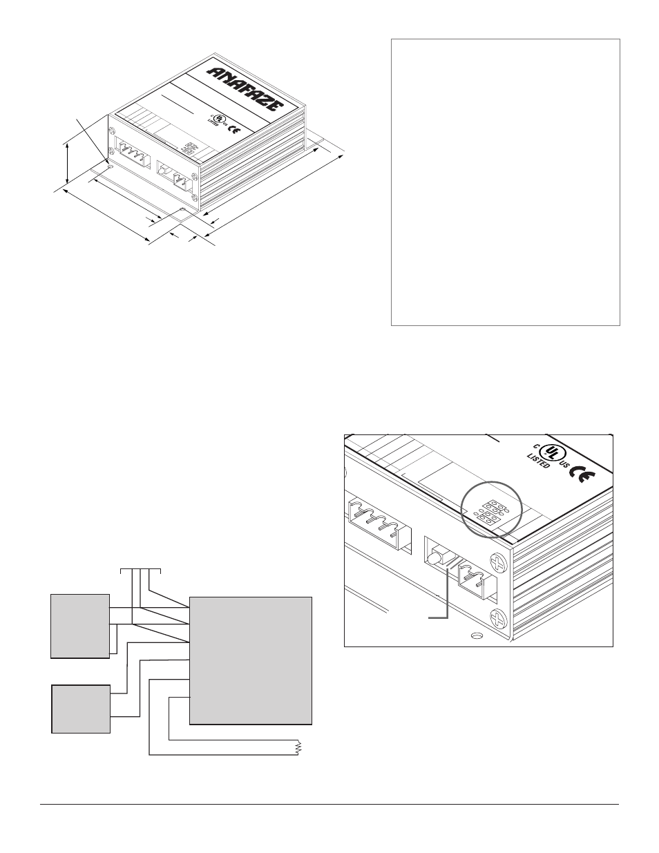
Figure 1. Serial DAC Dimensions
WARNINGS
Ó
WARNING
The SDAC module is for indoor use only. To reduce
the risk of fire or electrical shock, install in a con-
trolled environment relatively free of contaminants.
Ó
WARNING
Use a power supply with a Class 2 rating only.
NOTE
Tighten screw terminal connections to 0.5 to 0.6 Nm
(4.5 to 5.4 inch-pound).
NOTE
Use copper conductors only.