Troubleshooting wiring diagrams – Watlow SBL Card User Manual
Page 2
2
SBL Card Data Sheet
Troubleshooting
Wiring Diagrams
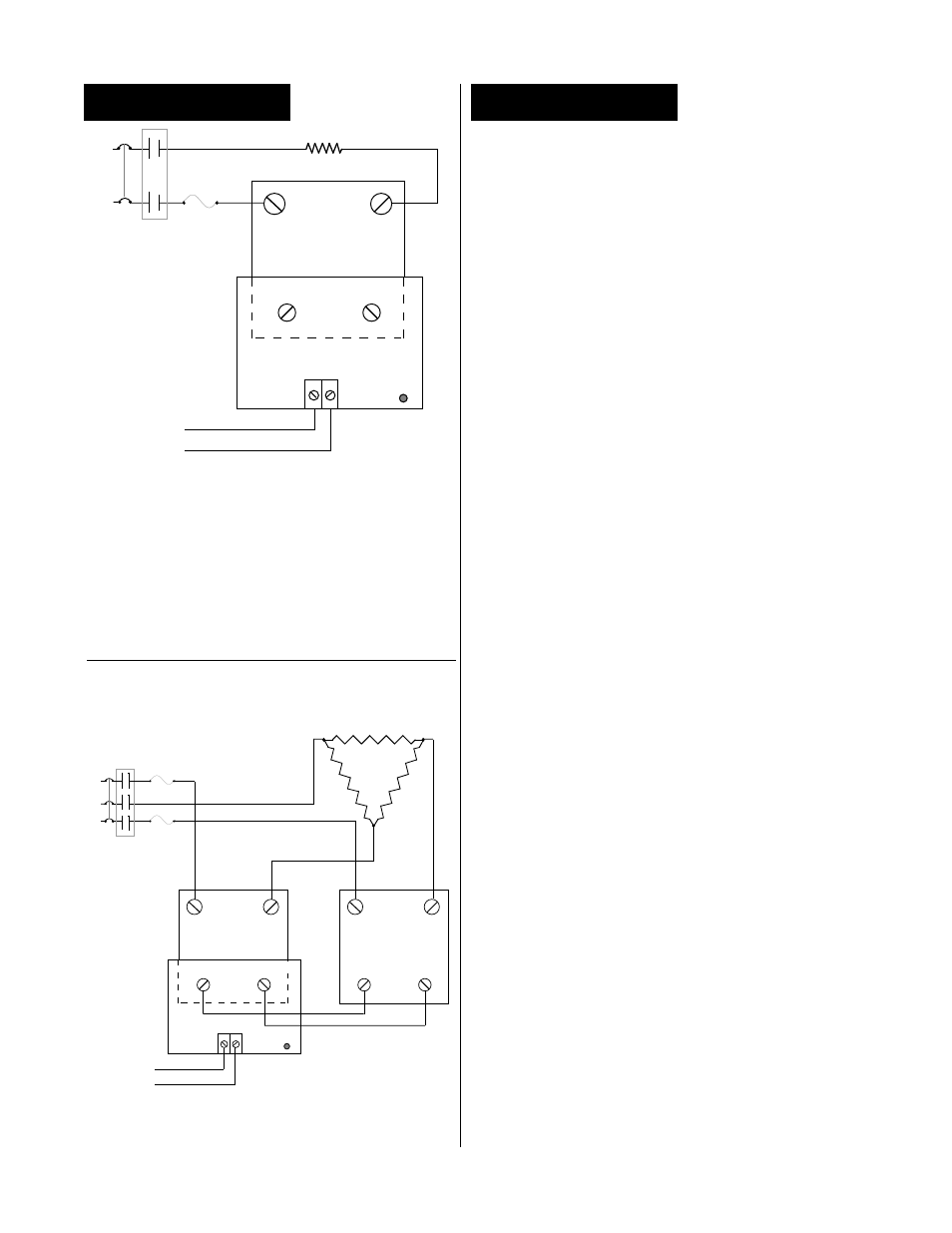
Three Phase, Two Leg
NOTE: The SBL Card can operate a maximum of 2
SSR's wired for 3 phase-2 leg control.
WARNING: Wiring examples show L2 in
240V~ (VAC) or 480V~ (VAC) configuration.
In 120V~ (VAC) or 277V~ (VAC) applications,
L2 is neutral and must not be fused or
switched. Failure to follow this guideline
could result in death or personal injury.
Single Phase
∫
∫
∫
∫
∫
Symptom
• No Output
Possible Causes
• No command signal
• No VAC to the heater
• Blown fuse
• Defective SSR
• Defective SBL
• Impedance mismatch
between temperature
control and SBL input
Troubleshooting Procedure
1. Make sure the “ON” LED located on the SBL card
is cycling or full ON. If not, check the 4-20mA
command signal. The SBL card requires at least
5mA to cycle. The SBL will not accept a voltage
input.
2. If the 4-20mA command signal is good and the
LED is cycling or full ON, check for VAC to the
heater. First, remove AC power from the system.
WARNING: Proceed with caution. The
remainder of step #2 has a potential shock
hazard. This is high voltage and is electrically
hot (120VAC or greater). Only qualified
electrical personnel should continue with
the remainder of this procedure.
Next, using an AC voltmeter, connect the volt-
meter leads across the heater terminals and
reapply power with the command signal at 20mA.
If there is no voltage present, remove power and
check for a blown fuse. To check for a blown fuse,
either replace the fuse, or measure it with an
ohmmeter and replace if necessary. The
ohmmeter should read around 0 ohms.
3. If the fuse is good, measure the voltage across the
terminals where the temperature control and SBL
connect. It should be 7.5 VDC minimum with the
input signal at 20mA. If the voltage is less, there
is probably an impedance mismatch between the
temperature control and SBL.
A quick way to check for an impedance mismatch
is to disconnect the SBL from the temperature
control. Replace the SBL with a 375
Ω
resistor,
and set the input signal to 20mA. Measure the
voltage across the resistor; it should be 7.5VDC
minimum. If the voltage is less than 3.5VDC @
4mA input signal, the SBL is defective and should
be returned for repair or replacement.
If the LED works on the SBL, but the SSR will not
turn on, there may be a mismatch between the
SBL and SSR. Try a different SSR.
∫
∫
∫
∫
∫
4-20mA
SSR
Output
S S R
Input
O N
L E D
SSR
Output
+
-
_
+
Limit
Contactor
Contacts
( If Required)
L 1
L 2
Semiconductor
Fuses
L 3
H e a t e r
S S R
Input
_
+
S B L
Heater
4-20mA Input
SSR
Output
SSR
Input
-
+
ON
LED
L1
L2
Limit Contactor
Contacts
( If Required)
Semiconductor
Fuse
+
-
SBL