Configuring dac outputs, Warnings – Watlow Dual DAC User Manual
Page 3
WATLOW DAC User’s Guide
3
Table 1A. DAC1 Jumper Settings
Table 1B. DAC2 Jumper Settings
Legend:
A: Load jumper in the “A” position, or load
jumper if header has only two pins.
B: Load jumper in the “B” position.
O: Open; do not load jumper.
Configuring DAC
Outputs
The DAC module ships with both outputs
configured for the signal type and span
ordered. The module contains two inde-
pendent circuits (DAC1 and DAC2). These
circuits can be configured for different out-
put types by changing the jumper settings
for one or both outputs. The odd numbered
jumpers determine the signal from DAC1;
the even numbered jumpers determine the
output from DAC2.
To change the output ranges:
1.
Power down the system (if DAC is
already installed and wired).
2.
Ensure the DAC1 and DAC2 terminal
blocks or associated wires are labeled
so that you will know which terminal
block connects to which side of the
board if the module is already
installed and wired.
3.
Unplug the two terminal blocks.
4.
Depending on the installation, you
may need to unmount the DAC mod-
ule before proceeding. Remove the
four screws from the end plate on the
opposite side of the module from the
terminal blocks.
5.
If necessary, remove the two mounting
screws holding the loosened end plate
in place.
6.
Slide the board out of the housing.
7.
Set the jumpers for the two outputs
as desired. See Tables 1A and 1B.
8.
Replace the board such that the con-
nectors extend through the opposite
end plate. The board fits in the third
slot from the bottom.
9.
Reconnect the two terminal blocks to
the DAC1 and DAC2 connectors.
10. Replace the end plate, end plate
screws and, if necessary, mounting
screws.
11. Check the wire connections to the
DAC1 and DAC2 terminal blocks.
12. If necessary, change the wiring con-
nections to the correct configuration
for the new output type.
13. Restore system power if the system
was powered down in Step 1.
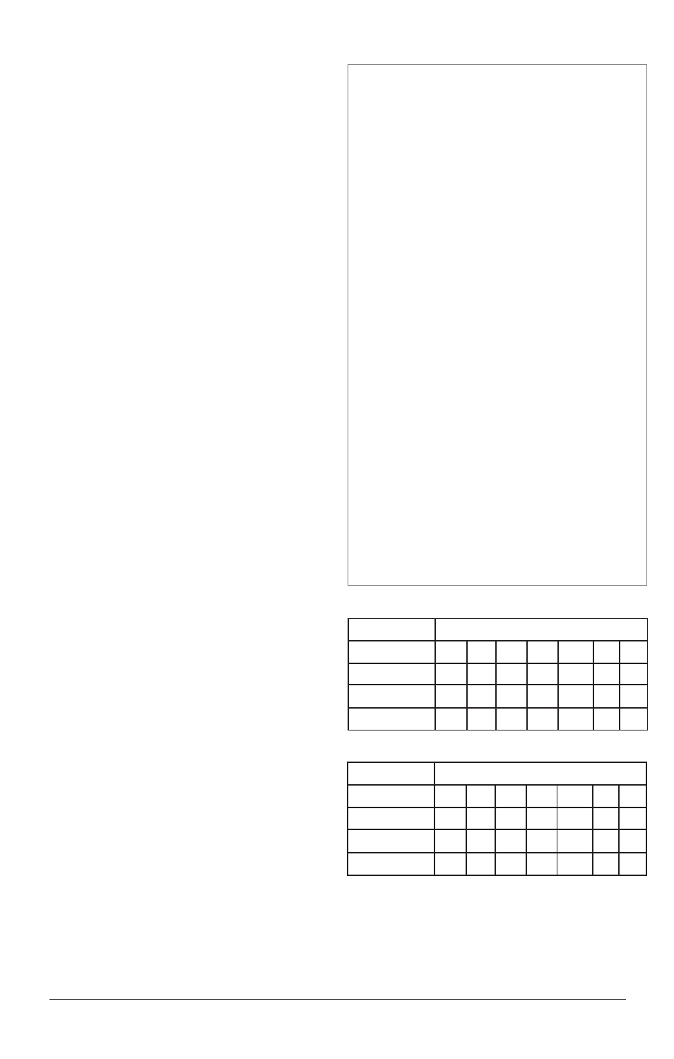
WARNINGS
Ó
WARNING
The DAC module is for indoor use only. To reduce the
risk of fire or electrical shock, install in a controlled
environment relatively free of contaminants.
Ó
WARNING
Use a power supply with a Class 2 rating only.
NOTE
Tighten screw terminal connections to 0.5 to 0.6 Nm
(4.5 to 5.4 inch-pounds).
NOTE
Use copper conductors only.
NOTE
Use the DAC only with appropriately sized loads.
See the Specifications section for minimum and
maximum allowable impedances.
ç
CAUTION
To avoid the RF interference problems that frequent-
ly accompany motor speed control circuits, do not
use power from the controller. Use a separate power
supply.
Jumper Settings
Output Signal
1
3
5
7
9
11
13
0 to 5VÎ (dc)
B
A
A
O
B
A
O
0 to 10VÎ (dc)
B
A
A
O
B
O
O
4 to 20 mA
O
A
B
A
A
O
A
Jumper Settings
Output Signal
2
4
6
8
10
12
14
0 to 5VÎ (dc)
B
A
A
O
B
A
O
0 to 10VÎ (dc)
B
A
A
O
B
O
O
4 to 20 mA
O
A
B
A
A
O
A