Val-Matic Cam-Centric Plug Valve User Manual
Page 5
5
FLANGED ENDS: Flanged valves should be mated
with flat-faced pipe flanges equipped with resilient
gaskets. When ring gaskets are used, the bolt material
should be ASTM A307 Grade B of SAE Grade 2
Carbon Steel. Higher strength bolts may only be used
with full-face gaskets.
The valve and adjacent piping must be supported and
aligned to prevent cantilevered stress on the valve.
Lower valve into line using slings or chains around the
valve body. Lubricate the flange bolts or studs and
insert them around the flange. Lightly turn bolts until
gaps are eliminated.
The torquing of the bolts should then be done in
graduated steps using the cross-over tightening
method. Recommended lubricated torques for use
with resilient gaskets (75 durometer) are given in Table
2. If leakage occurs, allow gaskets to absorb fluid and
check torque and leakage after 24 hours. Do not
exceed bolt rating or crush gasket more than 50
percent of its thickness.
TABLE 2. FLANGE BOLT TORQUES
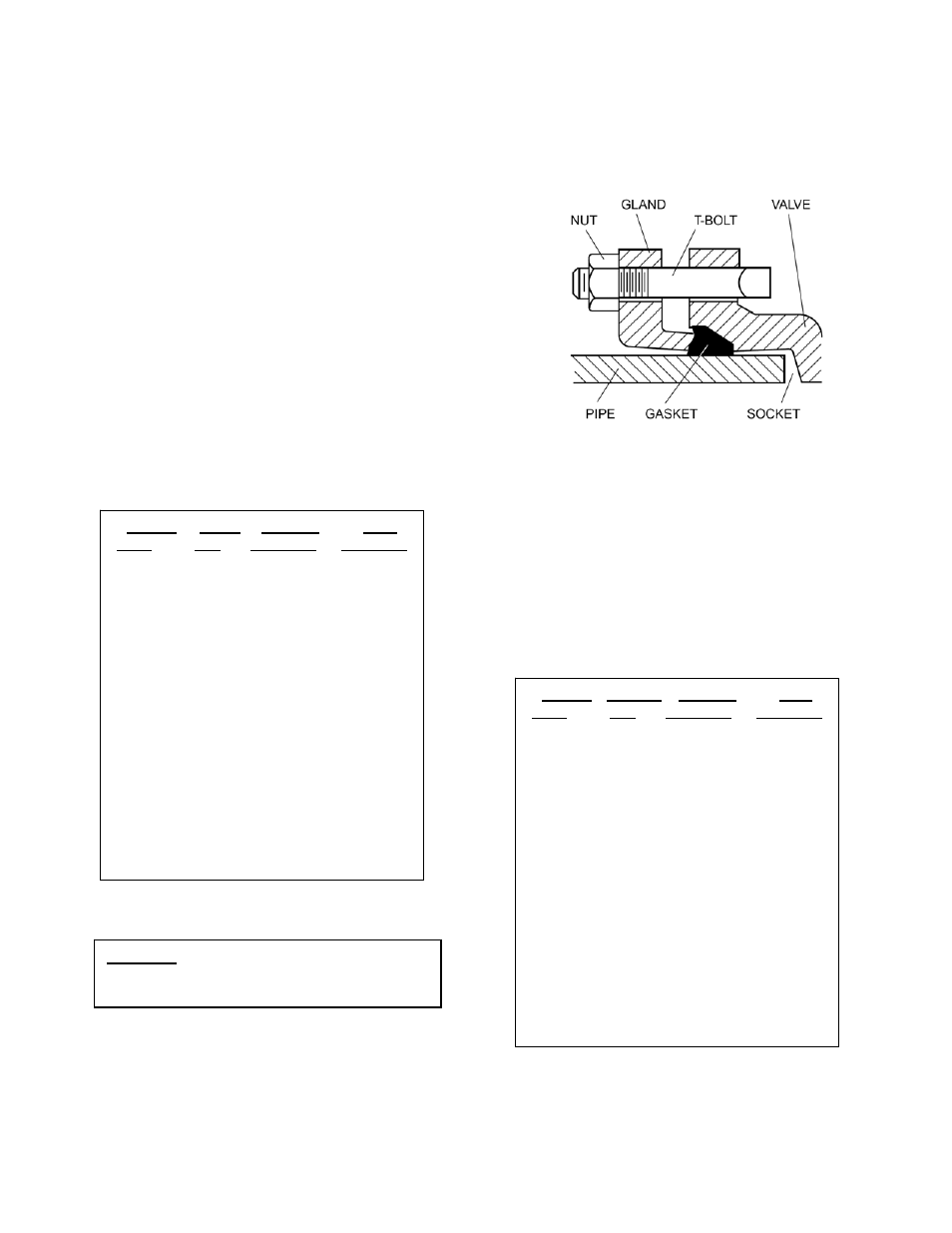
MECHANICAL JOINT ENDS: Clean ends of mating
pipe and valve sockets with soapy water (Figure 7).
Place lubricated gasket and retainer gland over pipe
end prior to installing valve. Install valve socket over
pipe. Press gland and gasket toward valve until gasket
is evenly set into valve socket.
FIGURE 7. MECHANICAL JOINT INSTALLATION
Insert T-bolts in valve flange and hand tighten nuts.
Torque nuts in four graduated steps using the cross-
over tightening method without exceeding the torque
listed in Table 3. Maintain an equal gap between the
gland and the face of the valve at all points around the
socket.
If a tight connection is not achieved, then the joint
should be disassembled, thoroughly cleaned, and
reassembled. Over-tightening may cause damage to
the valve or gland.
TABLE 3. MECHANICAL JOINT NUT TORQUES
VALVE BOLT RECOM
MAX
SIZE DIA TORQUE
TORQUE
(in)
(in) (ft-lbs)
(ft-lbs)
3
5/8 25
90
4
5/8 30
90
6
3/4 30
150
8
3/4 40
150
10
7/8 45
205
12
7/8 65
205
14
1
80
300
16
1
90
300
18
1 1/8 100
425
20
1 1/8 120
425
24
1 1/4 150
600
30
1 1/4 175
600
36
1 1/2 175
1000
42
1 1/2 200
1000
48
1 1/2 250
1000
CAUTION: The use of raised-face flanges
or excessive bolt torque may
damage valve flanges.
VALVE T-BOLT RECOM
MAX
SIZE DIA TORQUE
TORQUE
(in)
(in) (ft-lbs)
(ft-lbs)
3
5/8 45
60
4
3/4 75
90
6
3/4 75
90
8
3/4 75
90
10
3/4 75
90
12
3/4 75
90
14
3/4 75
90
16
3/4 75
90
18
3/4 75
90
20
3/4 75
90
24
3/4 75
90
30
1
100
120
36
1
100
120
42
1-1/4 75
150
48
1-1/4 75
150