Series l 5000 cord reels, Installation instructions, Adjusting the spring tension – Reelcraft Series L5000 Cord Reels User Manual
Page 2: Troubleshooting instructions
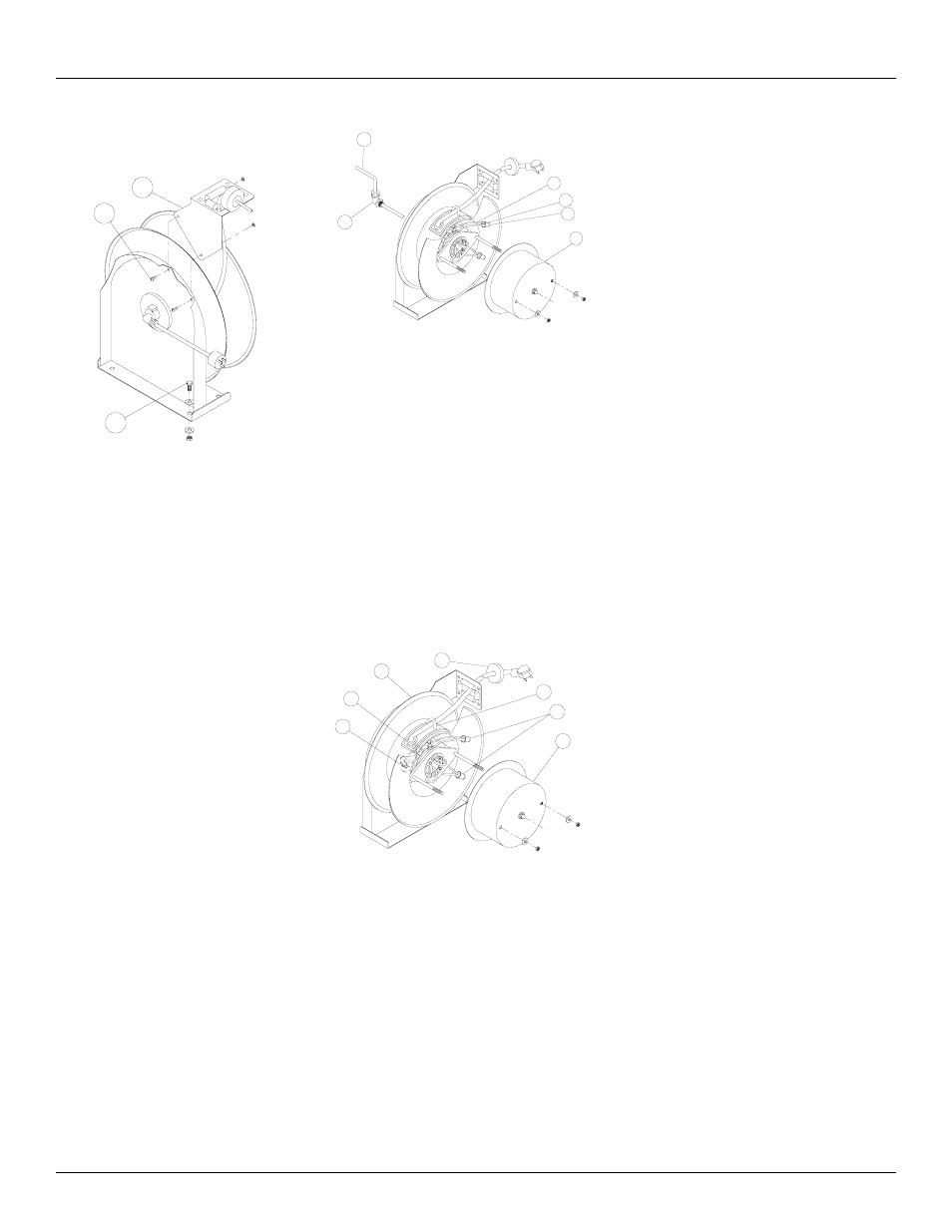
Series L 5000 Cord Reels
Page 2
www.reelcraft.com
Installation Instructions
Mounting
CAUTION:
Unless reel was specified differently when
ordering, maximum installation height is 16
feet. Do not exceed this distance. Ensure
that only a qualified electrician installs/
services this equipment. Observe applicable
NEC, OSHA, and local codes when install-
ing this equipment. Installation of GFCI cord
reels should be performed by a qualified and
licensed professional in accordance with local
building codes and applicable NEC standards.
1. Unpack and inspect the reel for damage.
Turn by hand to check for smooth opera-
tion. Check for completeness.
2. Configure reel for top, side or bottom-
wind (bottom-wind for constant tension
reels only) electrical cable dispensing by
removing bolts (1) securing guide arm
bracket (2).
3. Determine new guide arm bracket loca-
tion and remove corresponding bolts.
Position guide arm bracket to reel and
replace bolts.
4. Position reel on floor, wall or ceiling.
Secure into place using four (customer
supplied) screws or bolts (3).
Installing the Input Electrical Cable:
30 AMP Models
WARNING:
Use only 10/3 cable for input wiring. Ensure
that application does not exceed electrical rat-
ing of reel. (See page 1 of this manual).
1. Feed input cable (1) through elbow (2)
and main shaft.
2. Screw elbow (2) into reel.
3. Connect input wires (3) and collector
ring wires (4) together using wire nuts
(5).
4. Assemble cover (6) to reel.
Installing the Output Electrical
Cable: 30 AMP Models
WIRE COLOR CODE
Black-Hot
White-Neutral
Green-Ground
WARNING:
Select output cable in accordance with power
requirement of apparatus to be supplied.
Ensure that application does not exceed
electrical rating of reel (see page 1 of this
manual). Use extreme caution, reel under ten-
sion. Avoid releasing latch mechanism.
1. Manually turn sheave (7) until spring is
tight, back off 2 turns, and latch.
2. Remove access cover (8).
3. Remove 6” of output electrical cable
outer jacket.
4. Route cable through guide arm and
U-clamp (9) then through cut-out (10)
in spool.
5. Tighten U-clamp (9).
6. Using wire nuts (11), connect output
electrical cable wires to collector assem-
bly brush wires as indicated in illustra-
tion.
7. Connect ground wire of output electrical
cable to ground lug (12) located on inner
side of spool.
8. Using ohmmeter, check for ground faults.
9. Replace access cover (8). Release latch
and wind output electrical cable onto
reel.
10. Install cable bumper (13).
Adjusting the Spring Tension
If necessary, adjust spring tension on reel by
adding or removing wraps of electrical cord
from spool, one wrap at a time, until desired
tension is obtained. Add wraps to increase
tension. Remove wraps to decrease tension.
WARNING:
When adding wraps of electrical cord, be care-
ful not to exceed the winding mechanism’s
spring capacity. Add just enough wraps of
cord to achieve the desired tension. Damage
to the winding mechanism will result if spring
is over-tightened. Always be aware of spring
tension on reel. Exercise extreme caution.
Troubleshooting Instructions:
30 AMP Models
Troubleshooting of the reel consists of
isolating a problem to a defective electrical
cord/work device, brush holder/brushes, or
collector assembly. Refer any other
discrepancies only to an authorized service
person or directly to Reelcraft.
WARNING:
The following procedure directs the techician
to take voltage measurements. Remember,
even low voltage is dangerous and can cause
personal injury or death. Exercise extreme
caution! Ensure that only a qualified electrician
installs/services this equipment.
1
2
3
1
2
3
4
5
6
12
10
7
13
9
11
8